Download Arduino IDE: Visit the official Arduino website: Arduino Software. Choose the appropriate version for your operating system (Windows, macOS, Linux), and download the installer.
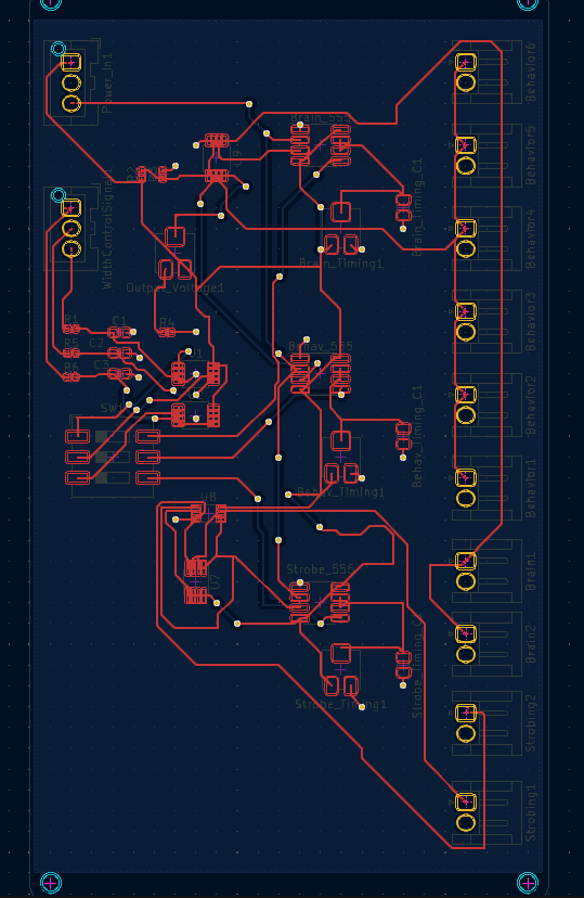
555Trigger is an open-source printed circuit board by ubcbraincircuits, from the ubcbraincircuits/Mesoscope-Resources repository on GitHub. It is a 2-layer board of 63.5 × 112.3 mm with 41 parts on 30 nets, routed with 413 tracks and 47 vias.
It is built around the 74AHC2G00DC and 74LVC2G74DP. Its parts include 6 resistors, 5 ICs, 3 capacitors and 1 switch.
Download Arduino IDE:
    Visit the official Arduino website: Arduino Software.
    Choose the appropriate version for your operating system (Windows, macOS, Linux), and download the installer.

Install Arduino IDE:
    Run the downloaded installer and follow the on-screen instructions.
    On Windows, you might need to install drivers for the Arduino board during the installation process.

Open Arduino IDE:
    Once installed, open the Arduino IDE.
Installing and Running a Supplied Program:
text
Connect Arduino Board:
    Connect your Arduino board to your computer using a USB cable.

Select Board and Port:
    In the Arduino IDE, go to Tools > Board and select the appropriate Arduino board (e.g., Arduino Uno).
    Also, go to Tools > Port and select the port to which your Arduino board is connected.

Open a Supplied Program (Sketch):
    Download the sketch from TriggeringstrobingArduinoCode/
    In the Arduino IDE, go to File > open and open the downloaded sketch

Verify the Sketch:
    Click the checkmark icon (Verify) to check for any errors in the code. Fix any errors if they occur.

Upload the Sketch:
    Click the right arrow icon (Upload) to compile and upload the sketch to the Arduino board.
Lens Adapters
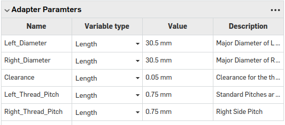
All the lens adapters are parametrically created using this onshape file:
Adjust these parameters to change the adapters parameters, the diameter is the inner diameter of the lens, pitch is usually 0.5 or 0.75
Strobing Trigger
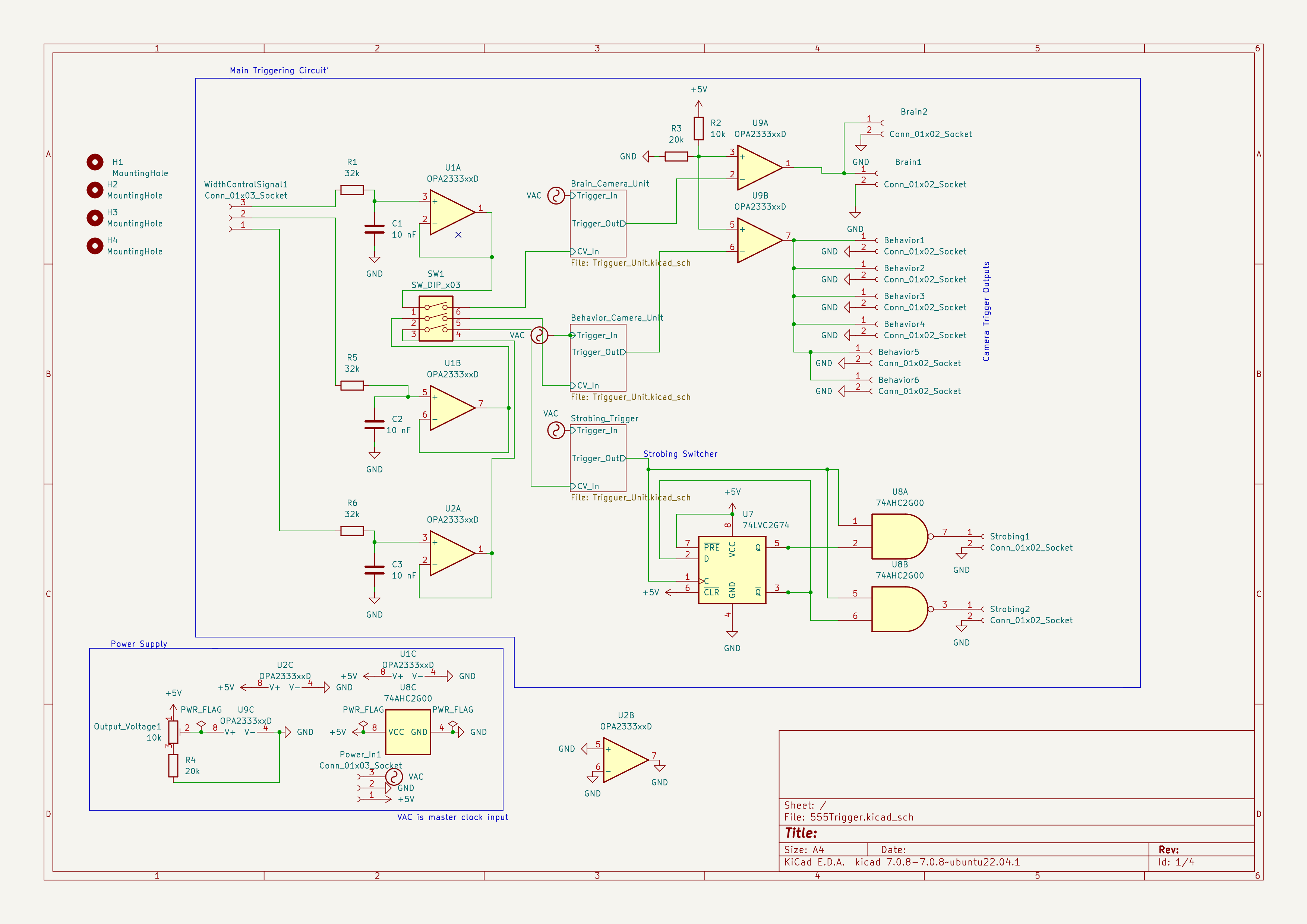
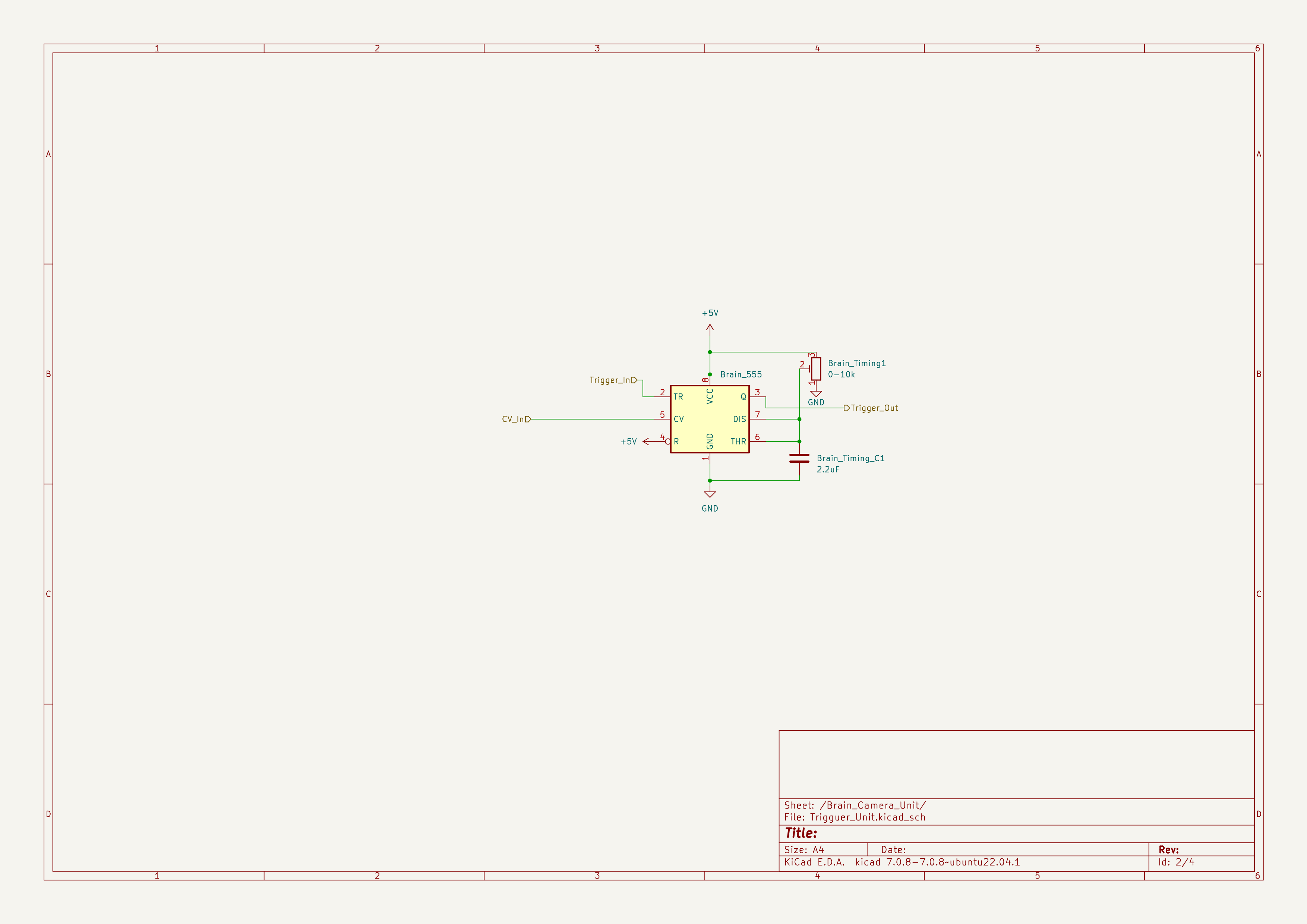
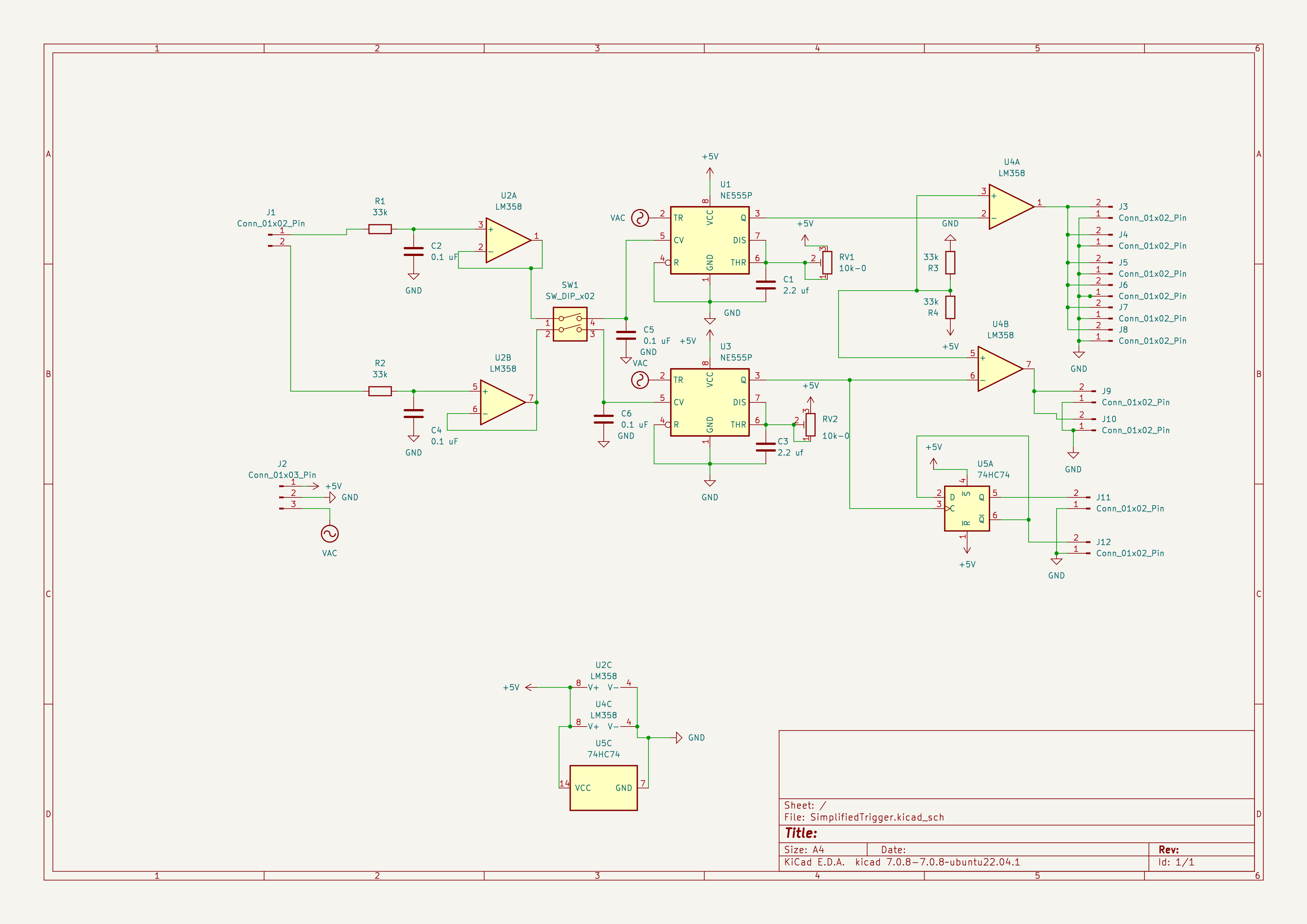
Circuit Diagrams
Triggering Unit
Routing
I/O
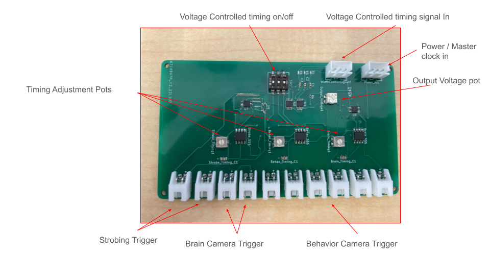
For the Master Clock in / power in pin out from left to right is
master clock
ground
power (5v)
for Timing signal the pinout is
Brain timing control
Behavior timing control
Strobing timing control
with the switches controlling in the same order.
In order to control the width of the timing signal supply a pwm signal to each of the width control signals, with the width corresponding to change in signal. The supplied signal should be greater than 1khz and ideally as high frequency as possible to reduce artifacts
the timing and output pots allow for manual control of timing and output voltage, although each of them can cause errors if pushed to their limits due to variation in their ranges from manufacturing. Never turn the timing pots all the way to the right as that might cause a short
Using
To use supply a 50hz PWM signal to the master clock with as wide a PWM as possible, the width of the signal corresponding to the maximum possible exposure time.
Supply a 5khz PWM signal for each width control pin in to control the exposure for brain and the behaviour cameras independently. Make sure the switch is switched to ON for the control pin being used. The Width of the PWM signal corresponds with the timing, with the widest signal being the longest exposure time.
import time

# Set GPIO mode and warning
GPIO.setmode(GPIO.BCM)
GPIO.setwarnings(False)

# Define the pin numbers
master_clock_pin = 17
width_control_pin = 18

# Set the frequency for the master clock (50Hz)
master_clock_frequency = 50

# Set the duty cycle for the master clock (99% width)
master_clock_duty_cycle = 99

# Set the frequency for the width control (5kHz)
width_control_frequency = 5000

# Initialize the GPIO pins
GPIO.setup(master_clock_pin, GPIO.OUT)
GPIO.setup(width_control_pin, GPIO.OUT)

# Initialize PWM for master clock
Throughole Based Triggering System
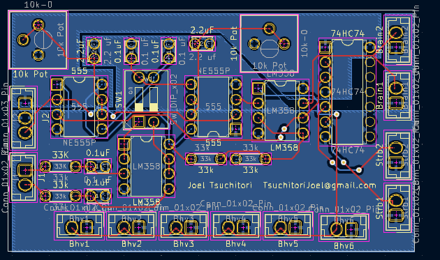
For making the throughhole 555 trigger there is a .xlsx file with the digikey order needed to create one system. The list can also be found at this link: https://www.digikey.ca/en/mylists/list/3F61W3LRA3. Then the components can be placed on the board based on the silkscreen.
Circuit Drawing
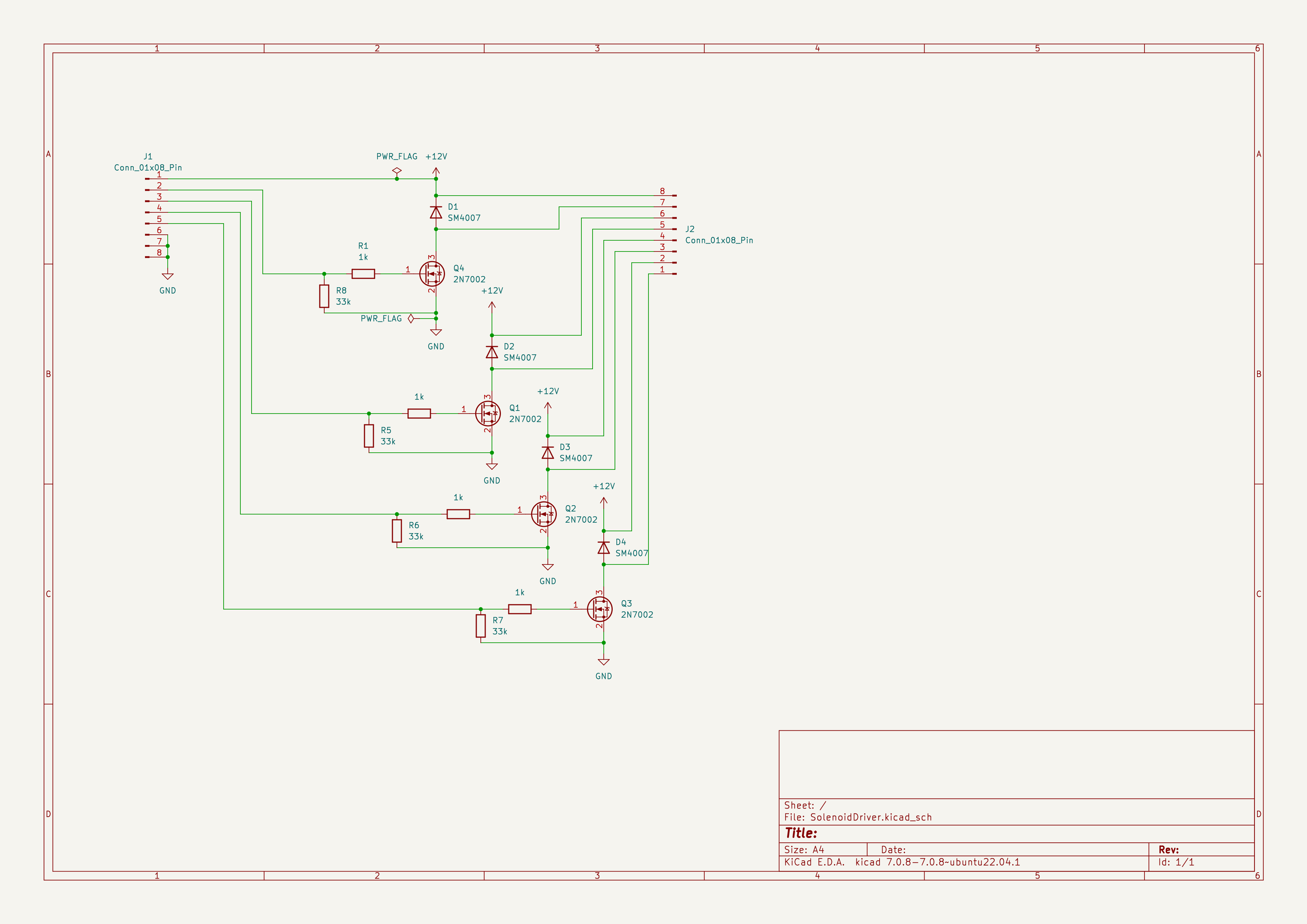
Solenoid Driver
The Driver is based on using M7 Mosfet drivers, which max out at ~300 mA of current draw at 12V, anything higher will damage and burn out the driver over time. Not suitable for high power solenoids.
the Glass Slide Cutting Jig is parameterized by a variable table which determines the depth of the first and second cuts, made to cut 8mm diameter glass slides, should be 3d printed on fine print settings.
It measures 63.5 × 112.3 mm and has 2 copper layers, 1.6 mm thick.
What parts does the 555Trigger use?
41 parts, built around the 74AHC2G00DC and 74LVC2G74DP. The full list of its parts is on this page, with links to each part's symbol and footprint where PCBKit's library has them.
Where can I download the 555Trigger KiCad files?
From the ubcbraincircuits/Mesoscope-Resources repository on GitHub, at the commit this page was made from: the board is 555Trigger/555Trigger.kicad_pcb and its schematic 555Trigger/555Trigger.kicad_sch. PCBKit opens the board in the browser, with nothing to install.
Can I use the 555Trigger design in my own project?
Its repository states no licence, so its author keeps all rights: ask ubcbraincircuits before reusing the design.
Download Arduino IDE: Visit the official Arduino website: Arduino Software. Choose the appropriate version for your operating system (Windows, macOS, Linux), and download the installer.