
4 layers234 × 84 mm
Main panel
google/mozc-devices
Circuit diagrams and firmware source code for Gboard DIY keyboards
234 parts3kApache-2.0

 anayksha/SlantPad
github repo for a macro pad I made for Hackpad by Hack Club
SlantPad is an open-source printed circuit board by anayksha, from the anayksha/SlantPad repository on GitHub, published under the GPL-3.0 licence. It is a 2-layer board of 67.1 × 67.5 mm with 37 parts on 35 nets, routed with 284 tracks and 191 vias.
It is built around the SK6812MINI-E. Its parts include 21 diodes, 10 switches and 1 IC. It belongs with the RP2040 boards of this library.
So this is a really interesting looking macropad that I will primarily be using to CAD on Onshape.
The most distinctive feature is that the OLED and rotary encoder are mounted on the front at an angle and will be attached to the PCB by soldering wires from the PCB to the components.
Note: I took heavy inspiration from Sam Liu's Square Pad.
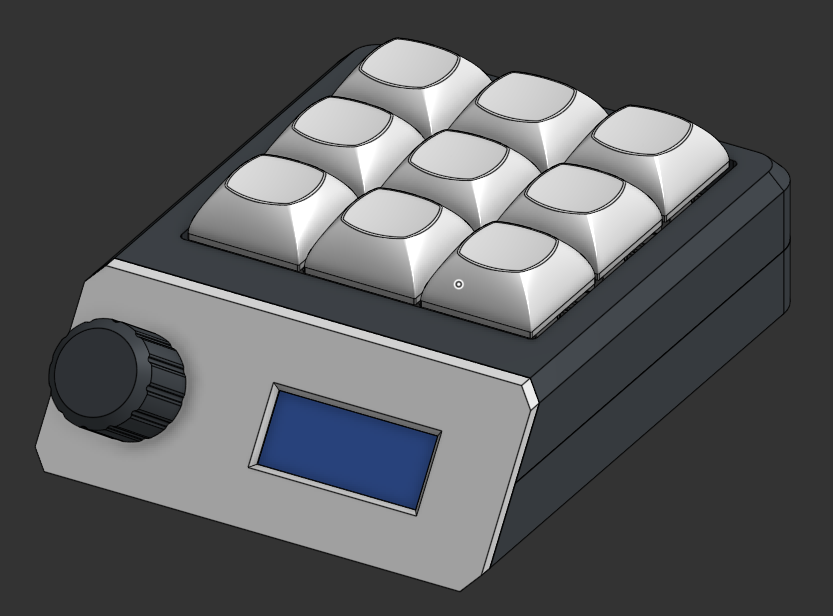
The case was modeled in Onshape and can be viewed here.
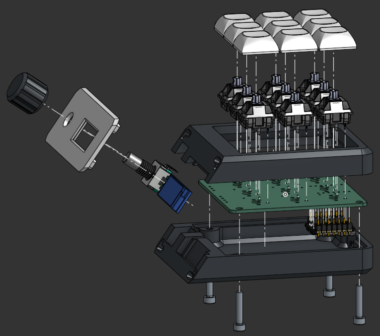
Behind the front cover of the case, there are slots in both the bottom and top parts that allow the rotary encoder and screen to fit.
There are 2 holes on the sides of the slot for the EC11, this so that the mounting pins on the EC11 can be pushed in and it can be snapped into place. There are 2 other pins on the EC11 for the onboard button, but I will be cutting those off because I am not using them.
There is a deeper rectanglular slot in the slot for the OLED, and this is so that the components on the back of the OLED's PCB can fit. A channel on the side of the OLED slot leading to the main chamber of the case will allow wires to go through from the OLED to the main PCB.
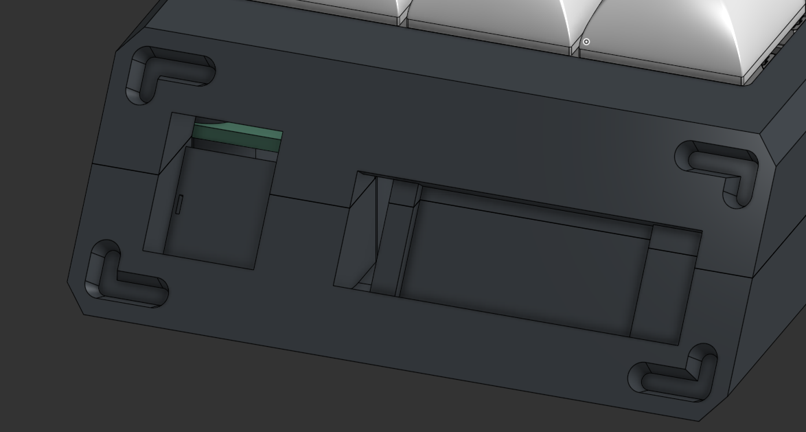
The L shaped slots in the corners have corresponding protrusions in the front cover that make it easier to line up and glue the front cover on
Why I am permanently mounting the front cover on: I couldn't figure out how to screw the front cover on bc heatset inserts take up a lot of space and there's like no space at the front and I havent made a snap fit 3D print before and I thought that now is not the time to mess with clearances.
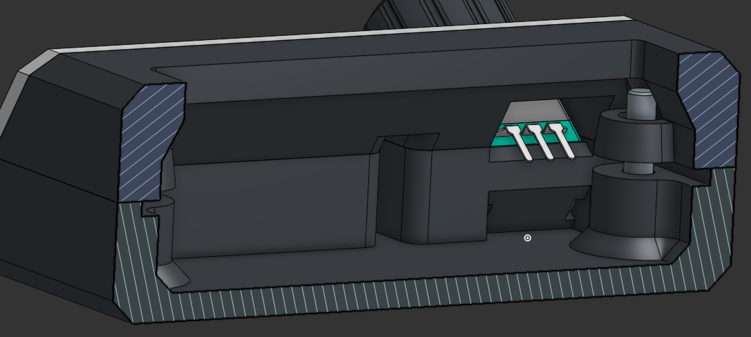
Also, I will probably be bending 3 main pins of the EC11 with pliers so they fit better in the case.
Unfortunately I can't make a clean pcb for my life and I couldn't figure out how to connect everything without excessively spamming vias and then via stitching the ground planes together on top of that.
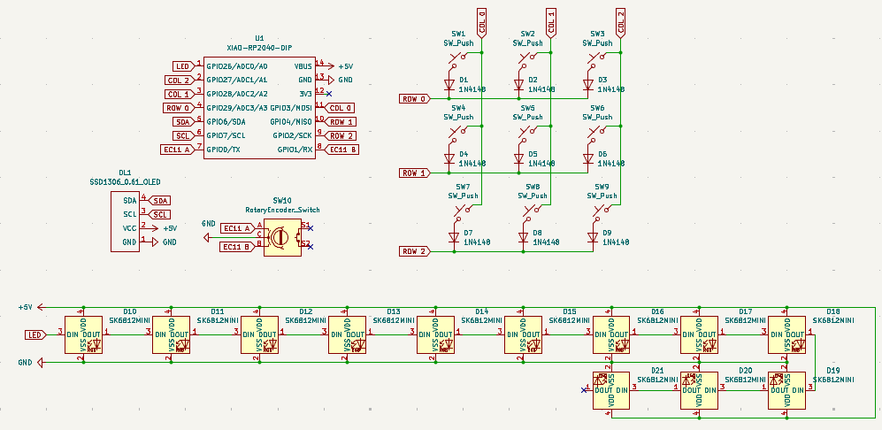
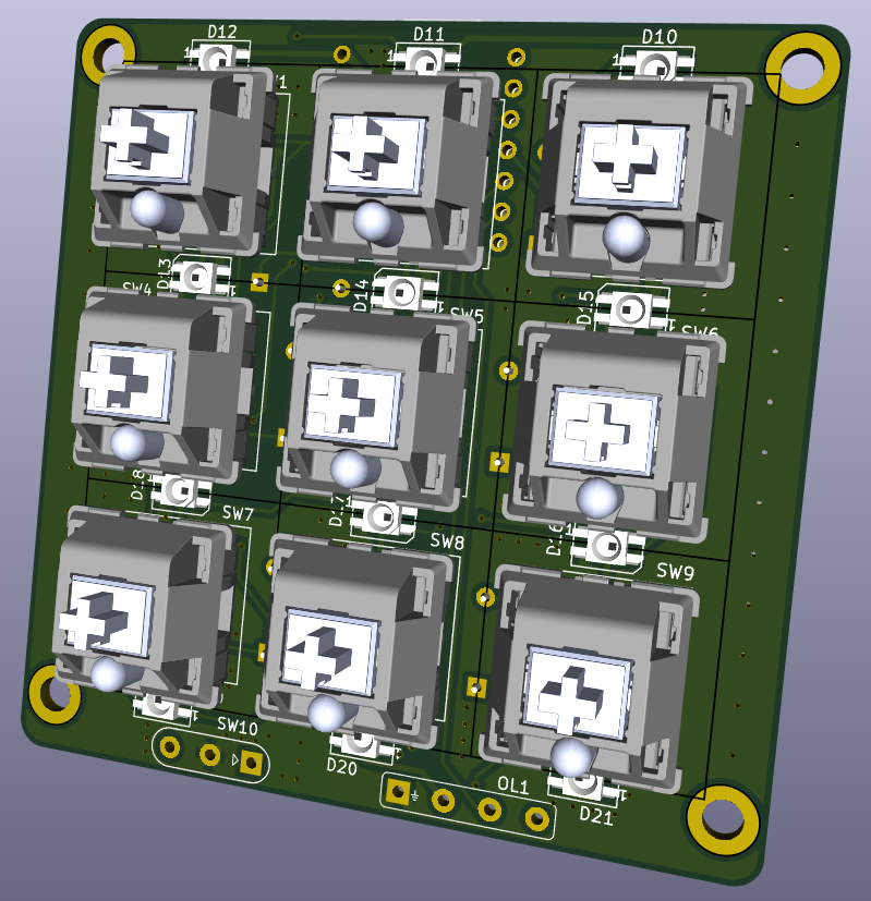
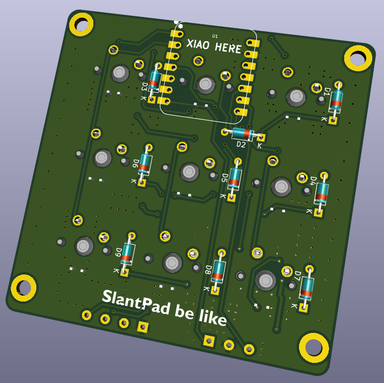
The XIAO RP2040 will be soldered to the back with header pins on.
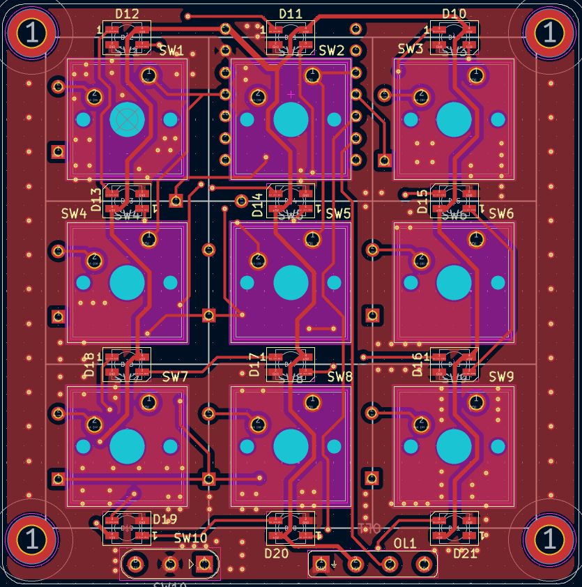
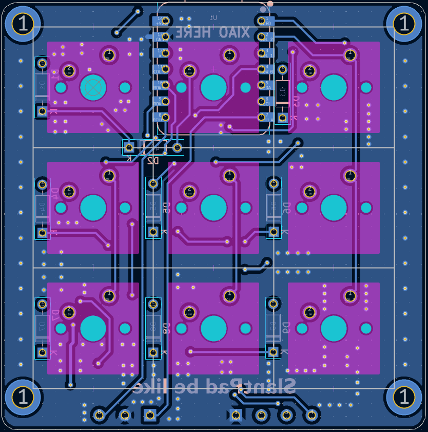
| Qty | Value | Footprint | References |
|---|---|---|---|
| 12 | SK6812MINI | LED_SMD:LED_SK6812MINI_PLCC4_3.5x3.5mm_P1.75mm | D10, D11, D12, D13, D14, D15, D16, D17, D18, D19, D20, D21 |
| 9 | 1N4148 | Diode_THT:D_DO-35_SOD27_P7.62mm_Horizontal | D1, D2, D3, D4, D5, D6, D7, D8, D9 |
| 9 | SW_Push | Button_Switch_Keyboard:SW_Cherry_MX_1.00u_PCB | SW1, SW2, SW3, SW4, SW5, SW6, SW7, SW8, SW9 |
| 1 | RotaryEncoder_Switch | Wire_Connectors:Rotary_Encoder_Wire_Connector | SW10 |
| 1 | SSD1306_0.61_OLED | Wire_Connectors:SSD1306_0.91_OLED_Wire_Connector | OL1 |
| 1 | XIAO-RP2040-DIP | OPL:XIAO-RP2040-DIP | U1 |
The 33 most common of 37 parts.
google/mozc-devices
Circuit diagrams and firmware source code for Gboard DIY keyboards

Bastardkb/Dilemma
The Dilemma is a vertical stagger low-profile keyboard with mods.

Pwnsat/FlatSat
Flatsat v1.0 is a hardware based platform for aerospace cybersecurity research

adamws/kicad-kbplacer
KiCad plugin for automatic keyboard's key placement and routing

imchipwood/dumbpad
Simple 4x4 numpad with rotary encoder. Powered by QMK via ATmega32u4 Pro Micro

makerforgetech/modular-biped
An open source framework for creating a bipedal modular companion robot.


It measures 67.1 × 67.5 mm and has 2 copper layers, 1.6 mm thick.
37 parts, built around the SK6812MINI-E. The full list of its parts is on this page, with links to each part's symbol and footprint where PCBKit's library has them.
From the anayksha/SlantPad repository on GitHub, at the commit this page was made from: the board is PCB/SlantPad.kicad_pcb and its schematic PCB/SlantPad.kicad_sch. PCBKit opens the board in the browser, with nothing to install.
Its repository publishes it under the GPL-3.0 licence: you may reuse it on that licence's terms (keep the author's notice, and for a copyleft licence share your changes alike).