
2 layers
Sensor top
ammygo/open-vibration-node
Open hardware LoRaWAN vibration sensing node — on-device FFT/envelope analysis, local-first, no mandatory cloud
23 parts2MIT
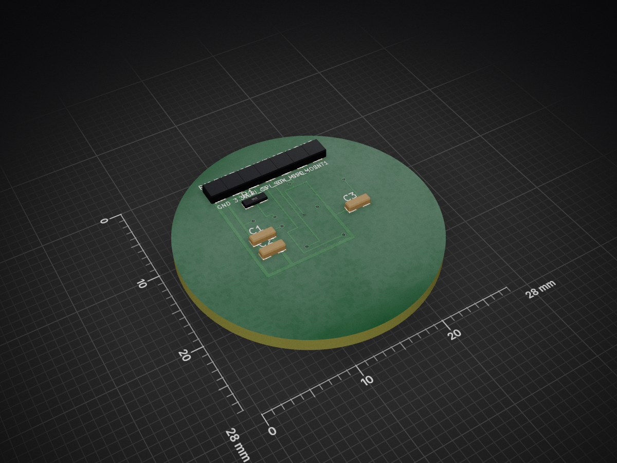
 ammygo/open-vibration-node2
Open hardware LoRaWAN vibration sensing node — on-device FFT/envelope analysis, local-first, no mandatory cloud
Sensor bottom is an open-source printed circuit board by ammygo, from the ammygo/open-vibration-node repository on GitHub, published under the MIT licence. It is a 2-layer board with 12 parts on 15 nets, routed with 67 tracks and 10 vias.
It is built around the IIS3DWB. Its parts include 3 capacitors, 1 resistor and 1 IC. It belongs with the radio and wireless and sensors and measurement boards of this library.
An open hardware and open firmware vibration sensing node for industrial condition monitoring — analysing vibration on the device and reporting results over LoRaWAN to a gateway you run yourself, with no mandatory cloud service.
Status: sensor board verified, radio path not yet exercised. The second-generation sensor board has been manufactured and verified on the bench — the sensor identifies correctly, gravity and impact-response tests pass, and the noise floor sits at ~18 mg RMS across the full 6.3 kHz bandwidth on a bench (measurements). The RAK3112 module has so far served only as the host MCU for those tests; the SX1262 radio has not yet been brought up. Mechanical integration and the signal-processing firmware are the current work.
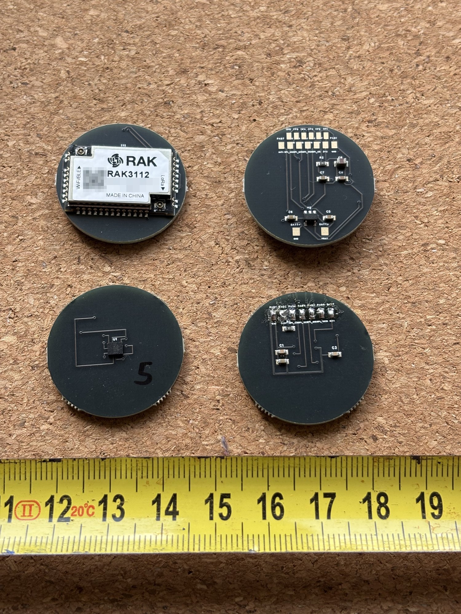
The two 28 mm boards that make up a node — sensor board and radio board, both sides. More photographs: docs/images.
Predictive maintenance works: measuring vibration on motors, bearings, pumps and fans reveals developing faults weeks or months before they cause a breakdown. The techniques are well documented in engineering literature, and the sensors cost a few euros.
Access to them is not open, though. Commercial condition-monitoring systems are closed end to end — proprietary sensors, proprietary gateways, and a vendor cloud that must stay reachable and paid for, or the equipment stops being monitored. Prices start in the hundreds of euros per measurement point, which puts continuous monitoring out of reach for small manufacturers, municipal utilities, water pumping stations and building services — exactly the operators who can least afford an unplanned failure.
Open vibration-monitoring projects do exist. The ones I have found stop at a development board on a desk, depend on a vendor cloud, or use accelerometers limited to a few hundred hertz — which rules out the 1–6 kHz region where bearing faults first appear. What is missing is a node that combines the bandwidth needed for real diagnostics with local-first operation and documentation good enough to rebuild it. This project aims to be that node.
| Approach | Usable bandwidth | Power / connectivity | Openness |
|---|---|---|---|
| Commercial condition-monitoring systems | Full (piezo-based) | Battery or wired; vendor cloud mandatory | Closed end to end; per-point pricing plus subscription |
| Open builds on consumer MEMS (ADXL345 / LIS3DH class) | ~200–800 Hz | Battery; various | Open, but physically blind to the 1–6 kHz bearing-fault region |
| Wired piezo + DAQ setups | Full | Mains power and cabling per point | Mixed; cabling dominates per-point cost |
| This project | DC–6.3 kHz (IIS3DWB) | Battery + LoRa; local-first, no mandatory cloud | Open: hardware, firmware, docs, production files |
Open lab-instrument projects — open microscopes, open test equipment — have already shown that laboratory-grade but open and rebuildable is a workable model. This project applies that model to industrial vibration monitoring.
These are the goals the design is being built towards, not a description of what already works — see the status above.
| Block | Part | Key figures |
|---|---|---|
| Accelerometer | STMicroelectronics IIS3DWB | DC–6.3 kHz flat bandwidth, 26.667 kHz ODR, 75 µg/√Hz noise density, ±2/4/8/16 g, SPI, −40…+105 °C, integrated temperature sensor |
| MCU + radio | RAK Wireless RAK3112 | ESP32-S3 + Semtech SX1262 in one certified module (LoRa 868 MHz, WiFi, BLE), 23×15 mm |
| Power | Diodes AP2112K-3.3 LDO | 600 mA, SOT-23-5 (LCSC C51118) |
IIS3DWB. Bearing and mechanical fault signatures live in the 1–6 kHz region, while ordinary MEMS accelerometers (ADXL345, LIS3DH and similar) are limited to 200–800 Hz — they physically cannot see what matters. The IIS3DWB gives a flat 6.3 kHz bandwidth at 75 µg/√Hz noise in a single 2.5 × 3.0 mm package, so diagnostics that previously required a piezoelectric accelerometer with an external conditioner now fit in a 28 mm node running from a battery.
RAK3112. The ESP32-S3 has enough compute to run the FFT locally, which is the whole premise of the design: the node transmits a spectral summary rather than raw waveforms, which is what makes both the battery budget and the LoRa duty cycle work. Combining it with the SX1262 in one certified module means a single component instead of MCU plus radio plus RF matching, and no antenna network to design. The trade-off is board area in exchange for reproducibility and a simpler certification path — a deliberate choice for a project that others are meant to be able to rebuild.
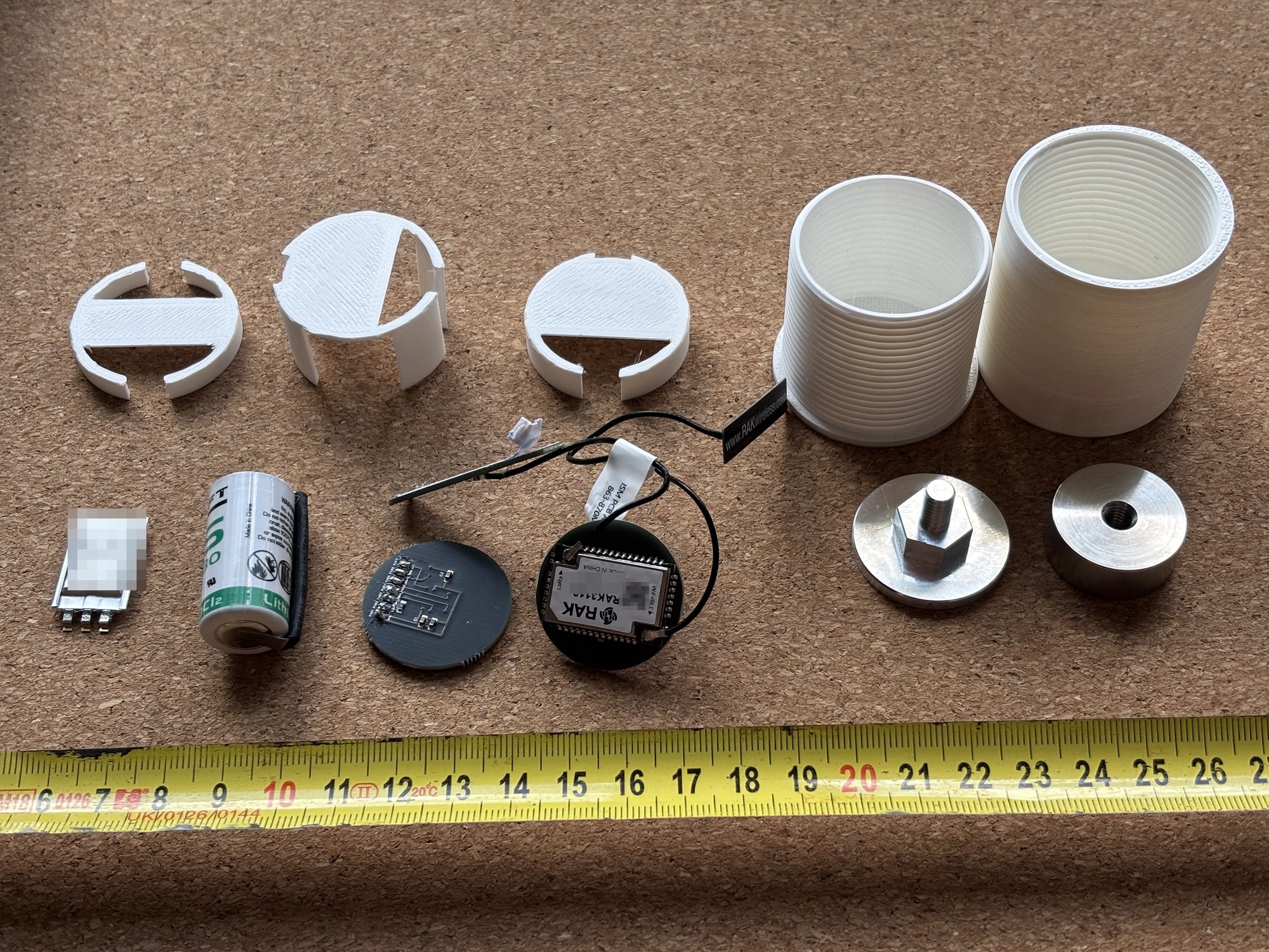
Everything that goes into one node: the two boards, primary cell, energy buffer, antennas, printed housing and the aluminium mounting pad.
Two 28 mm round boards with the battery between them, joined by seven wires:
Inter-board signals: GND, 3V3, SPI_CS, SPI_SCK, SPI_MISO, SPI_MOSI, INT1.
Pad order is identical on both boards, so the wires run straight across without crossing.
Placing the accelerometer on the bottom layer is deliberate — it shortens the mechanical path between the measured surface and the sensing element, which matters far more for signal fidelity than any amount of filtering afterwards.
A node normally sends only a spectral summary — a payload of a couple of dozen bytes, which is what makes years of battery life on a low-bandwidth radio possible at all. That summary is enough to trend a machine's condition, but not to investigate a fault in detail.
So the node keeps a second path. The RAK3112 carries 8 MB of PSRAM, enough to hold about 50 seconds of the full 26.667 kHz three-axis stream. When something in the trend needs looking at, an engineer standing next to the machine can trigger a capture and pull the raw recording off over WiFi, straight to a laptop — no cloud and no gateway involved. This path works on the bench as of September 2026: a downlink command makes the node record 32768 samples per axis (1.23 s — the PSRAM allows about 50 s; 1.23 s is the current capture length) from the sensor FIFO into PSRAM and post them over WiFi to the collector (the local server described above; a laptop also works), which it locates by mDNS.
This is deliberately on demand rather than continuous: streaming raw data would end the battery budget within days. Routine monitoring stays cheap; full detail is available when it is actually needed.
| Path | Contents |
|---|---|
firmware/tests/ | Bench verification sketches — sensor identification and acquisition |
docs/ | Measurements, payload specification draft, build notes |
enclosure/ | Mounting pad and housing — CAD sources with open-format exports |
tools/ | Design-check utilities: a mirrored-footprint checker and the velocity-RMS filter validation script |
hardware/ | KiCad boards plus gerbers, BOM and pick-and-place files for both boards |
hardware/LICENSE.txt)Timing is indicative and assumes part-time development; with project funding it compresses.
Built by Laurynas Misiūnas, an electronics engineer in Klaipėda district, Lithuania, with six years of industrial experience deploying edge AI vision systems and embedded controllers on production lines. Developed with the support of the Klaipėda Science and Technology Park (KMTP) innovation support programme.
Contributions, review and questions are welcome — see CONTRIBUTING.md or open an issue.
Engineering decisions, architecture and project direction in this repository are made by
the author. Documentation and English-language texts are drafted with the assistance of a
large language model (Anthropic Claude) and reviewed, corrected and approved by the author
before publication. Commits with LLM-assisted content carry a Co-Authored-By: Claude
trailer. Details in TRANSPARENCY.md.
No firmware, hardware design files or measurement data will be presented as project deliverables without human authorship and verification.
| Qty | Value | Footprint | References |
|---|---|---|---|
| 2 | 100nF | Capacitor_SMD:C_0603_1608Metric | C1, C3 |
| 1 | 10k | Resistor_SMD:R_0603_1608Metric | R1 |
| 1 | 1uF | Capacitor_SMD:C_0603_1608Metric | C2 |
| 1 | 3.3V | Connector_PinHeader_2.00mm:PinHeader_1x01_P2.00mm_Vertical | PAD2 |
| 1 | GND | Connector_PinHeader_2.00mm:PinHeader_1x01_P2.00mm_Vertical | PAD1 |
| 1 | IIS3DWB | Package_LGA:LGA-14_3x2.5mm_P0.5mm | U1 |
| 1 | INT1 | Connector_PinHeader_2.00mm:PinHeader_1x01_P2.00mm_Vertical | PAD7 |
| 1 | SPI_CS | Connector_PinHeader_2.00mm:PinHeader_1x01_P2.00mm_Vertical | PAD3 |
| 1 | SPI_MISO | Connector_PinHeader_2.00mm:PinHeader_1x01_P2.00mm_Vertical | PAD5 |
| 1 | SPI_MOSI | Connector_PinHeader_2.00mm:PinHeader_1x01_P2.00mm_Vertical | PAD6 |
| 1 | SPI_SCK | Connector_PinHeader_2.00mm:PinHeader_1x01_P2.00mm_Vertical | PAD4 |
12 parts, built around the IIS3DWB. The full list of its parts is on this page, with links to each part's symbol and footprint where PCBKit's library has them.
From the ammygo/open-vibration-node repository on GitHub, at the commit this page was made from: the board is hardware/sensor-board/sensor_bottom.kicad_pcb. PCBKit opens the board in the browser, with nothing to install.
Its repository publishes it under the MIT licence: you may reuse it on that licence's terms (keep the author's notice, and for a copyleft licence share your changes alike).
ammygo/open-vibration-node
Open hardware LoRaWAN vibration sensing node — on-device FFT/envelope analysis, local-first, no mandatory cloud

IslamHUFE/Mechanical-Vibrations-Analyzer
A compact mechanical vibration monitoring system designed to be mounted directly on a machine and visualize its vibration behavior as a real-time spectrogram.


melikeatilgan/asenkron-motor-bakim
15 kW asenkron motor için arıza ağacı analizi, aylık bakım formu ve KiCad'de tasarlanmış üç izleme kartı

jayis1/hardware-design-lab
Full-cycle hardware device designs — each device in its own subfolder with architecture, schematics, PCB layout, and software stack

Yexall/CPE-450.Capstone
Fall 24 - Winter 25 Cal Poly Capstone project by Haas Hooligans. This projects aims to build a machine monitoring system for the Cal Poly IME department.

github-linguist/linguist
Language Savant. If your repository's language is being reported incorrectly, send us a pull request!
