
4 layers80 × 80 mm

A compact mechanical vibration monitoring system designed to be mounted directly on a machine and visualize its vibration behavior as a real-time spectrogram.
Gyroscope is an open-source printed circuit board by IslamHUFE, from the IslamHUFE/Mechanical-Vibrations-Analyzer repository on GitHub. It is a 6-layer board of 100 × 50 mm with 39 parts on 64 nets, routed with 158 tracks and 182 vias.
It is built around the W25Q128JVSIQ, AP2112K-3.3 and IIS3DWB. Its parts include 15 capacitors, 11 resistors, 6 ICs, 2 connectors and 1 inductor. It belongs with the STM32 boards of this library.


A compact mechanical vibration monitoring system designed to be mounted directly on a machine and visualize its vibration behavior as a real-time spectrogram.
The device is designed around a custom PCB, a mechanical enclosure, and an embedded vibration-sensing system. After mounting the unit to a machine using screws, the machine can be operated while its vibration characteristics are displayed on the onboard screen as a frequency-versus-time spectrogram.
Project status: Hardware design completed.
The main idea of the project is to provide a self-contained vibration-monitoring device that can be physically attached to machinery and used to observe its vibration spectrum.
This makes it possible to visually observe how the machine's vibration spectrum changes over time.
The hardware was designed as a custom PCB specifically for the vibration-monitoring application. The repository contains the KiCad design files together with the supporting 3D/CAD files used during the mechanical design process.
The following renders show the assembled PCB from different viewing angles.
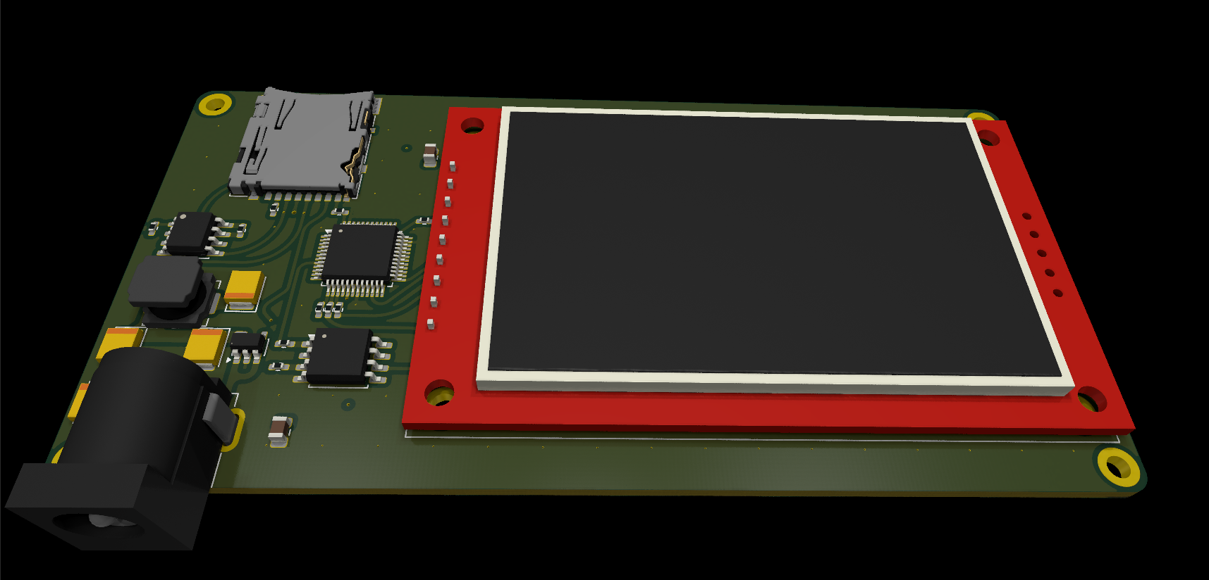 PCB 3D View — Front Perspective Three-dimensional view of the completed PCB from a front perspective. |
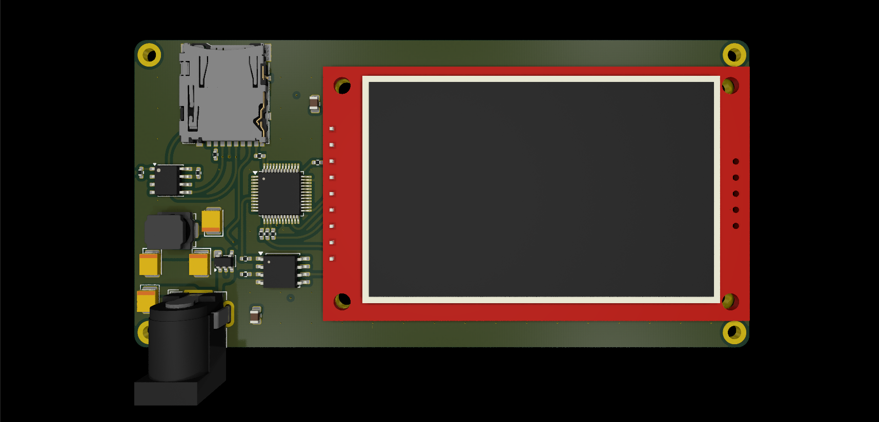 PCB 3D View — Rear Perspective Three-dimensional view showing the opposite side of the assembled board. |
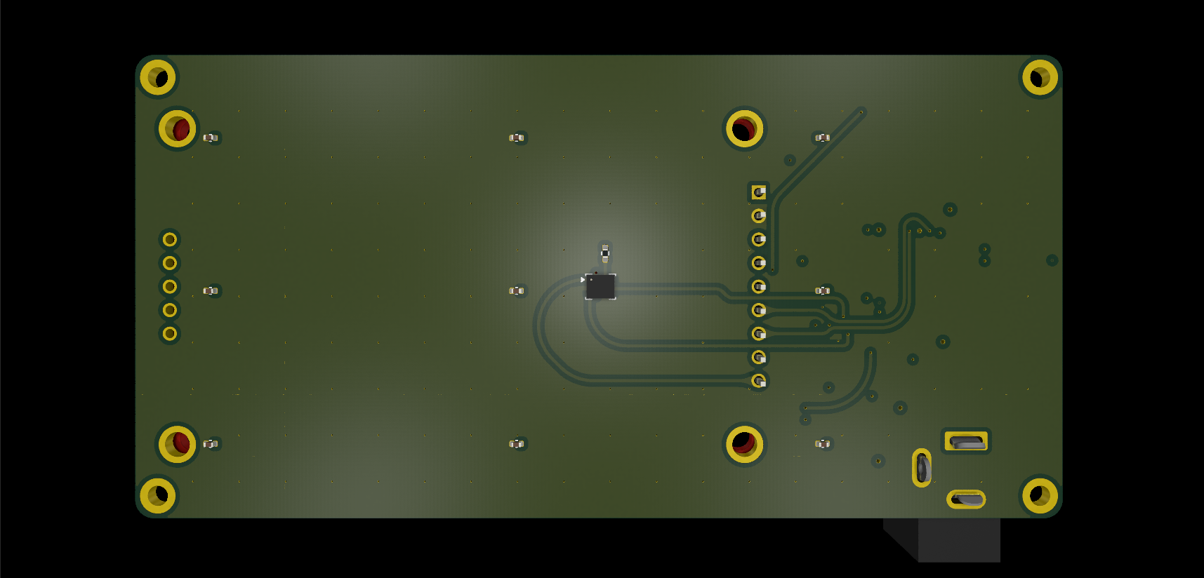 PCB 3D View — Overall Assembly Additional 3D perspective highlighting the board layout and component placement. |
The next renders show the complete PCB layer arrangement followed by the individual layers in order.
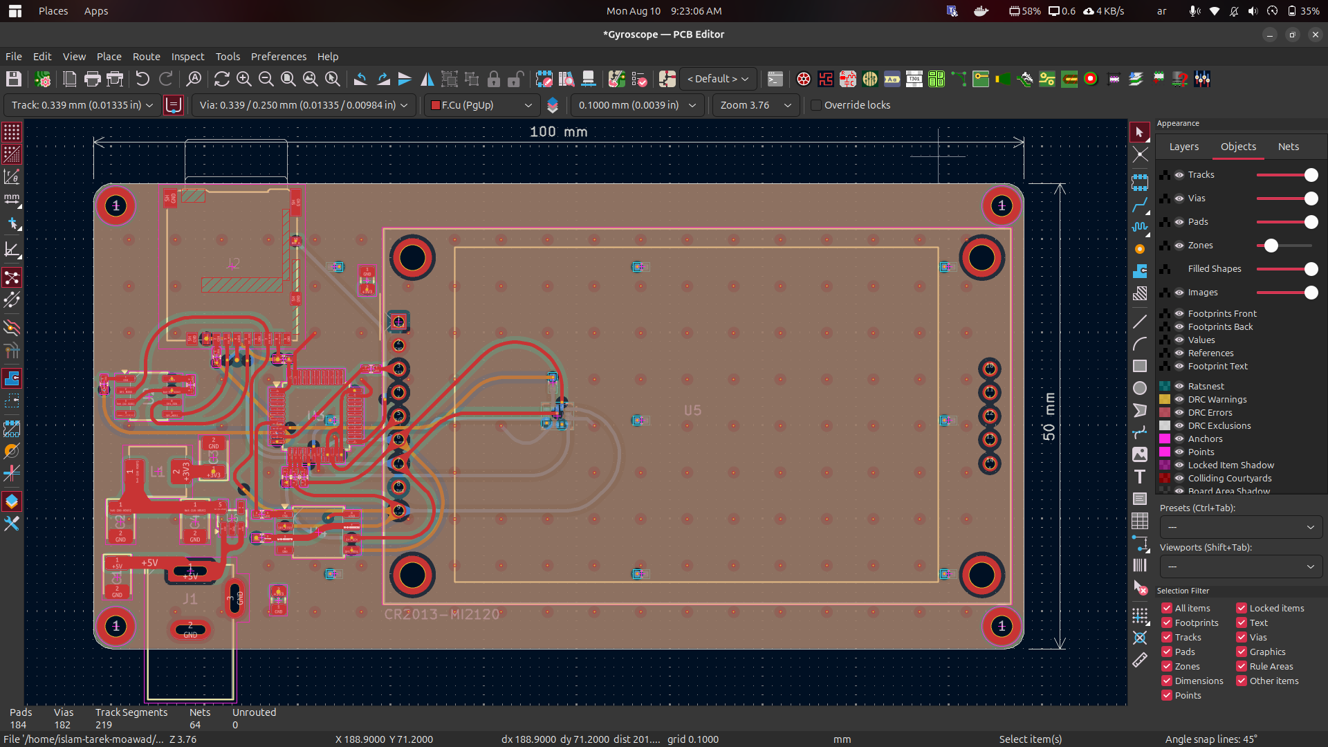 Complete PCB Layer Stack All six PCB layers shown together to illustrate the complete board layout. |
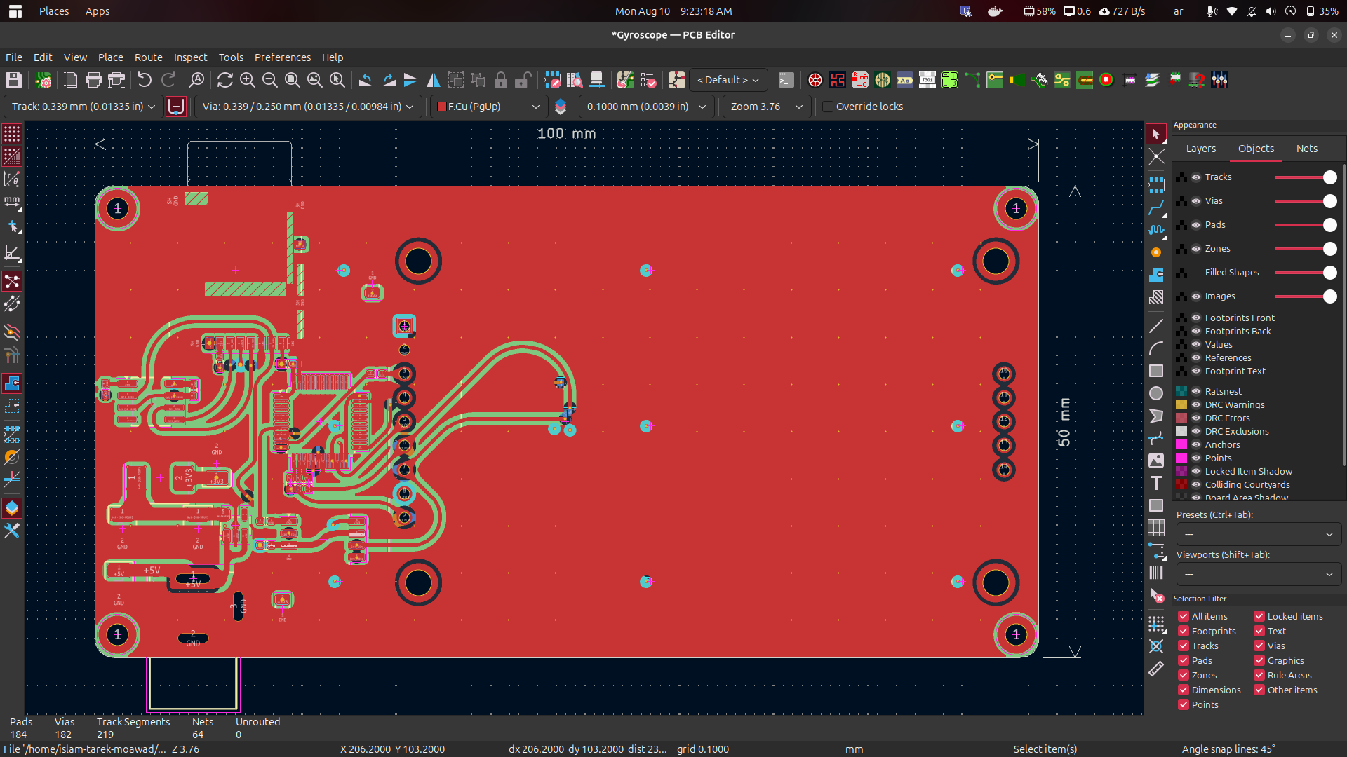 Layer 1 First individual PCB layer in the layer sequence. |
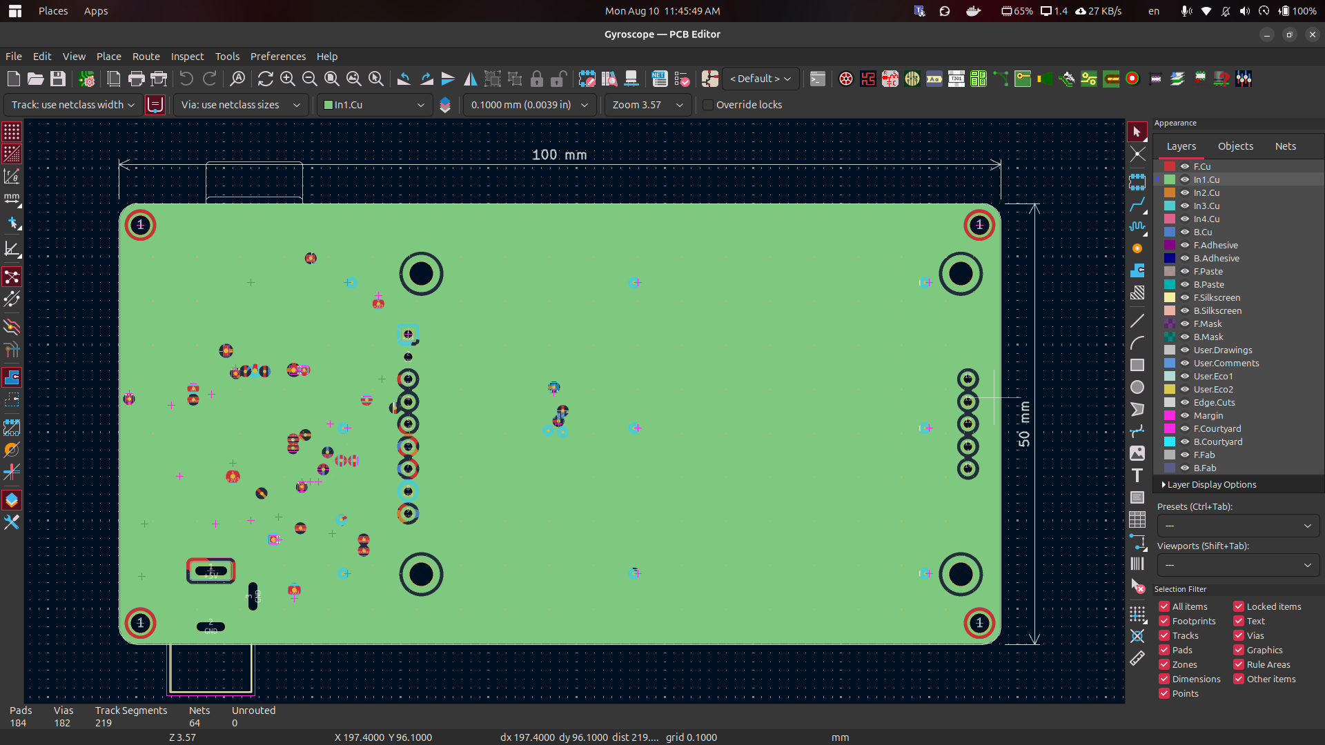 Layer 2 Second individual PCB layer in the layer sequence. |
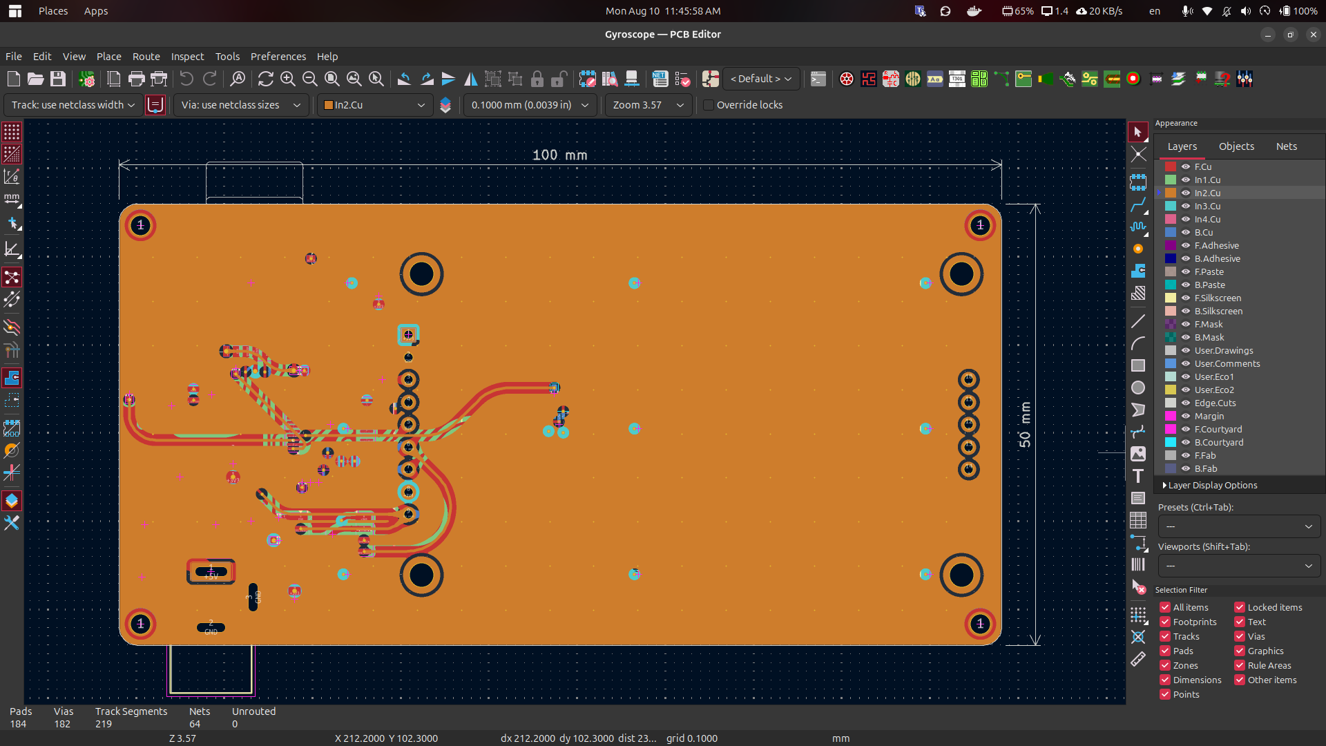 Layer 3 Third individual PCB layer in the layer sequence. |
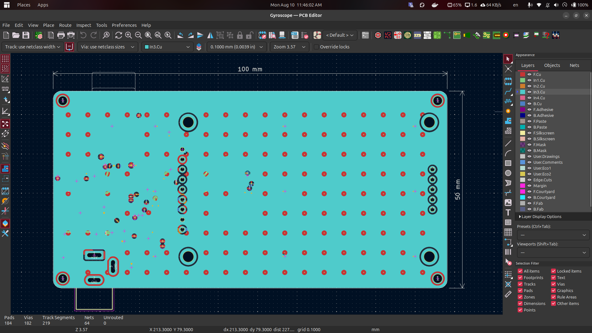 Layer 4 Fourth individual PCB layer in the layer sequence. |
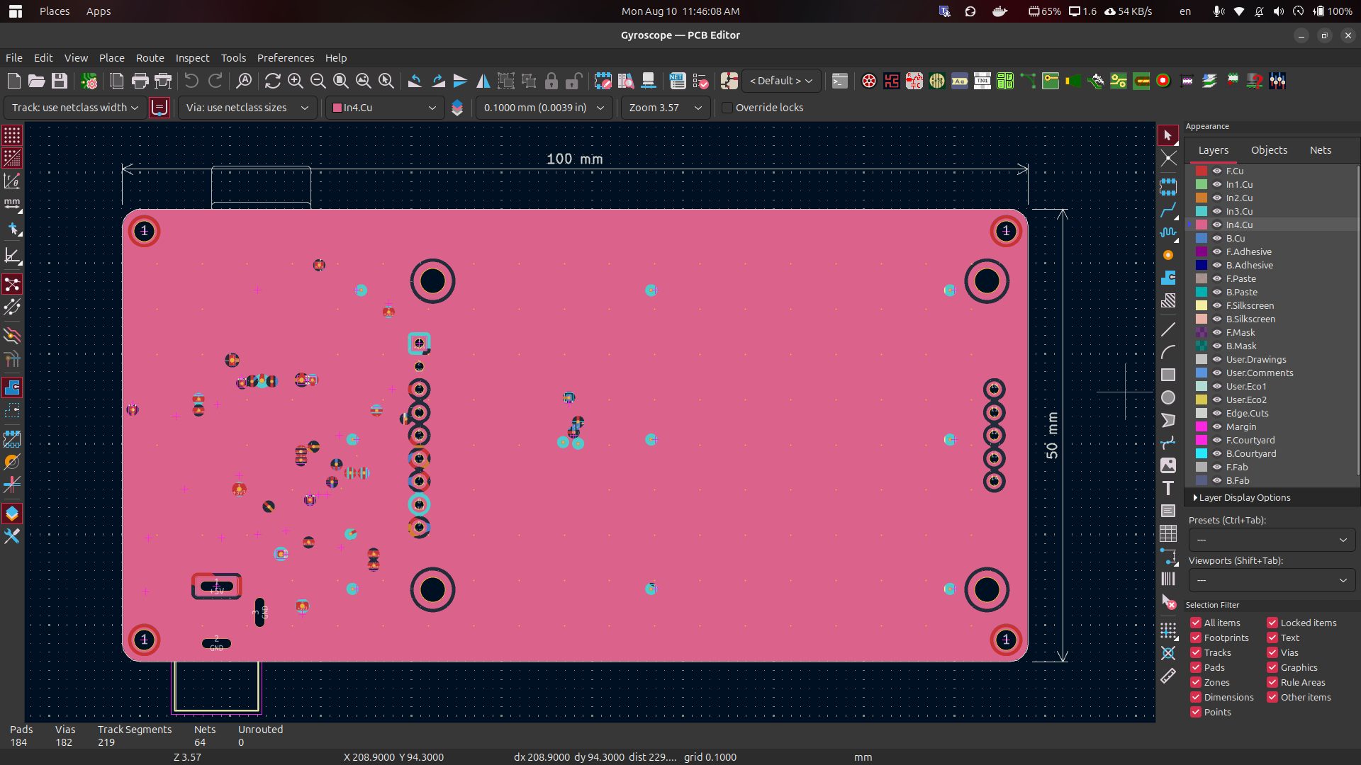 Layer 5 Fifth individual PCB layer in the layer sequence. |
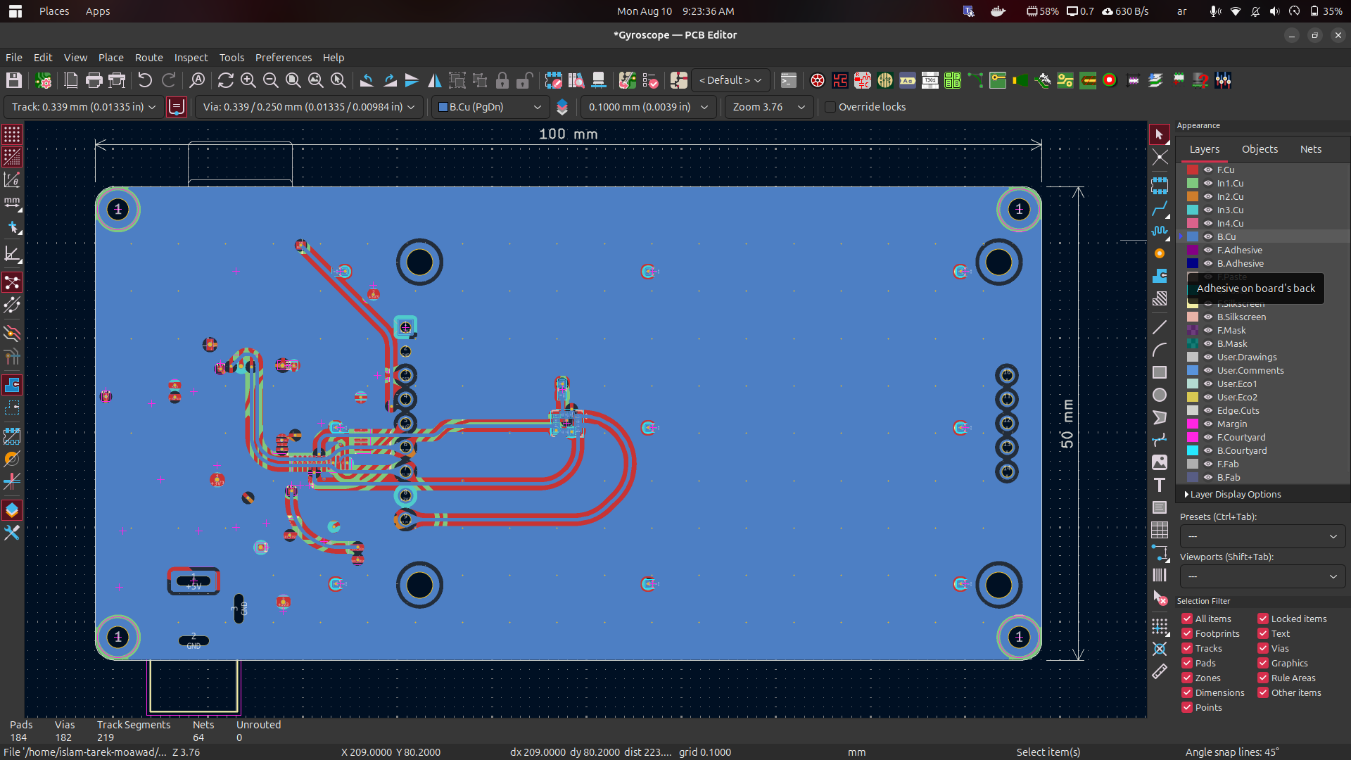 Layer 6 Sixth and final individual PCB layer in the layer sequence. |
A dedicated enclosure was designed for the PCB using FreeCAD. The enclosure provides a physical housing for the electronics and allows the analyzer to be securely mounted to the machine during measurements.
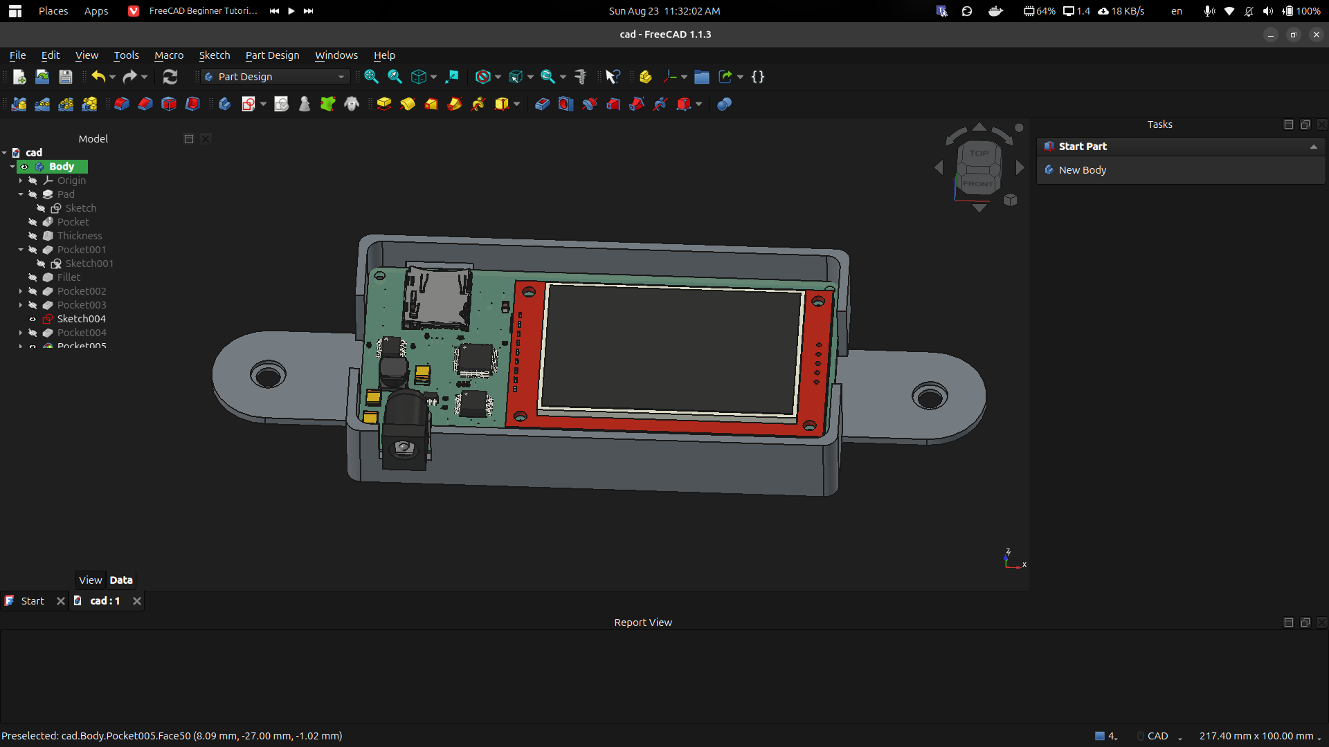 FreeCAD Enclosure — Design View CAD model of the custom enclosure designed around the PCB. |
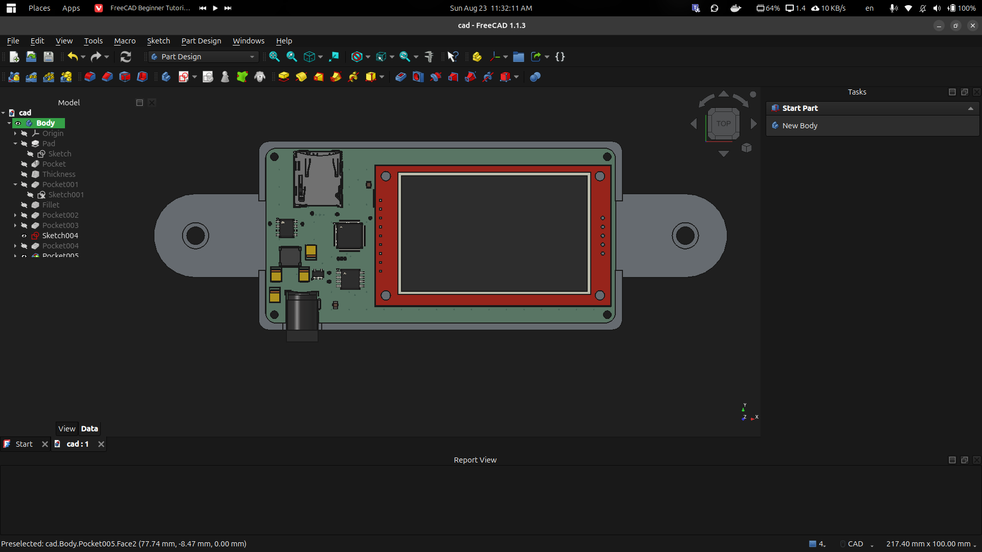 FreeCAD Enclosure — Final View Additional enclosure view showing the mechanical housing and mounting geometry. |
The repository includes the main hardware-design files used to develop the analyzer, including:
The analyzer can be used as a compact tool for observing vibration behavior in rotating or mechanically moving equipment. A spectrogram provides a convenient way to see both the frequency content and how it evolves over time.
Potential uses include:
More details about the hardware development and the project progress are available in the project's LinkedIn post:
Mechanical Vibrations Analyzer — Hardware Development
Islam Tarek Moawad
Designed and developed as an embedded hardware project combining PCB design, vibration sensing, signal analysis, embedded systems, and mechanical CAD.
| Qty | Value | Footprint | References |
|---|---|---|---|
| 11 | R_US | Resistor_SMD:R_0402_1005Metric_Pad0.72x0.64mm_HandSolder | R1, R2, R3, R4, R5, R6, R7, R8, R9, R10, R11 |
| 9 | 100n | Capacitor_SMD:C_0402_1005Metric | C6, C7, C9, C11, C12, C13, C14, C15, C16 |
| 4 | C_Polarized | Capacitor_Tantalum_SMD:CP_EIA-3528-12_Kemet-T | C1, C2, C3, C4 |
| 4 | MountingScrew | MountingHole:MountingHole_2.2mm_M2_DIN965_Pad_TopBottom | H1, H2, H3, H4 |
| 2 | 1u | Capacitor_SMD:C_0805_2012Metric | C8, C10 |
| 1 | AP2112K-3.3 | Package_TO_SOT_SMD:SOT-23-5 | U6 |
| 1 | APS6404L-3SQRx-SN | Package_SO:SOIC-8_3.9x4.9mm_P1.27mm | U2 |
| 1 | Barrel_Jack_Switch | Connector_BarrelJack:BarrelJack_GCT_DCJ200-10-A_Horizontal | J1 |
| 1 | CR2013-MI2120 | Display:CR2013-MI2120 | U5 |
| 1 | IIS3DWB | Package_LGA:LGA-14_3x2.5mm_P0.5mm_LayoutBorder3x4y | U1 |
| 1 | L | Inductor_SMD:L_Neosid_SM-PIC0512H | L1 |
| 1 | Micro_SD_Card_Det2 | Connector_Card:microSD_HC_Hirose_DM3AT-SF-PEJM5 | J2 |
| 1 | STM32G431C6Tx | Package_QFP:LQFP-48_7x7mm_P0.5mm | U3 |
| 1 | W25Q128JVS | Package_SO:SOIC-8_5.3x5.3mm_P1.27mm | U4 |


ammygo/open-vibration-node
Open hardware LoRaWAN vibration sensing node — on-device FFT/envelope analysis, local-first, no mandatory cloud

melikeatilgan/asenkron-motor-bakim
15 kW asenkron motor için arıza ağacı analizi, aylık bakım formu ve KiCad'de tasarlanmış üç izleme kartı

jayis1/hardware-design-lab
Full-cycle hardware device designs — each device in its own subfolder with architecture, schematics, PCB layout, and software stack

Yexall/CPE-450.Capstone
Fall 24 - Winter 25 Cal Poly Capstone project by Haas Hooligans. This projects aims to build a machine monitoring system for the Cal Poly IME department.


ianklug/grooveboard
A four-key mechanical keyboard for rhythm games.
It measures 100 × 50 mm and has 6 copper layers, 1.6 mm thick.
39 parts, built around the W25Q128JVSIQ, AP2112K-3.3 and IIS3DWB. The full list of its parts is on this page, with links to each part's symbol and footprint where PCBKit's library has them.
From the IslamHUFE/Mechanical-Vibrations-Analyzer repository on GitHub, at the commit this page was made from: the board is Gyroscope.kicad_pcb and its schematic Gyroscope.kicad_sch. PCBKit opens the board in the browser, with nothing to install.
Its repository states no licence, so its author keeps all rights: ask IslamHUFE before reusing the design.