
2 layers160 × 100 mm
MPCNC Nano Estlcam Shield
tnn85/MPCNC-Nano-Estlcam-Shield
Ein CNC Shield für die MPCNC in Verwendung mit Estlcam
96 parts70
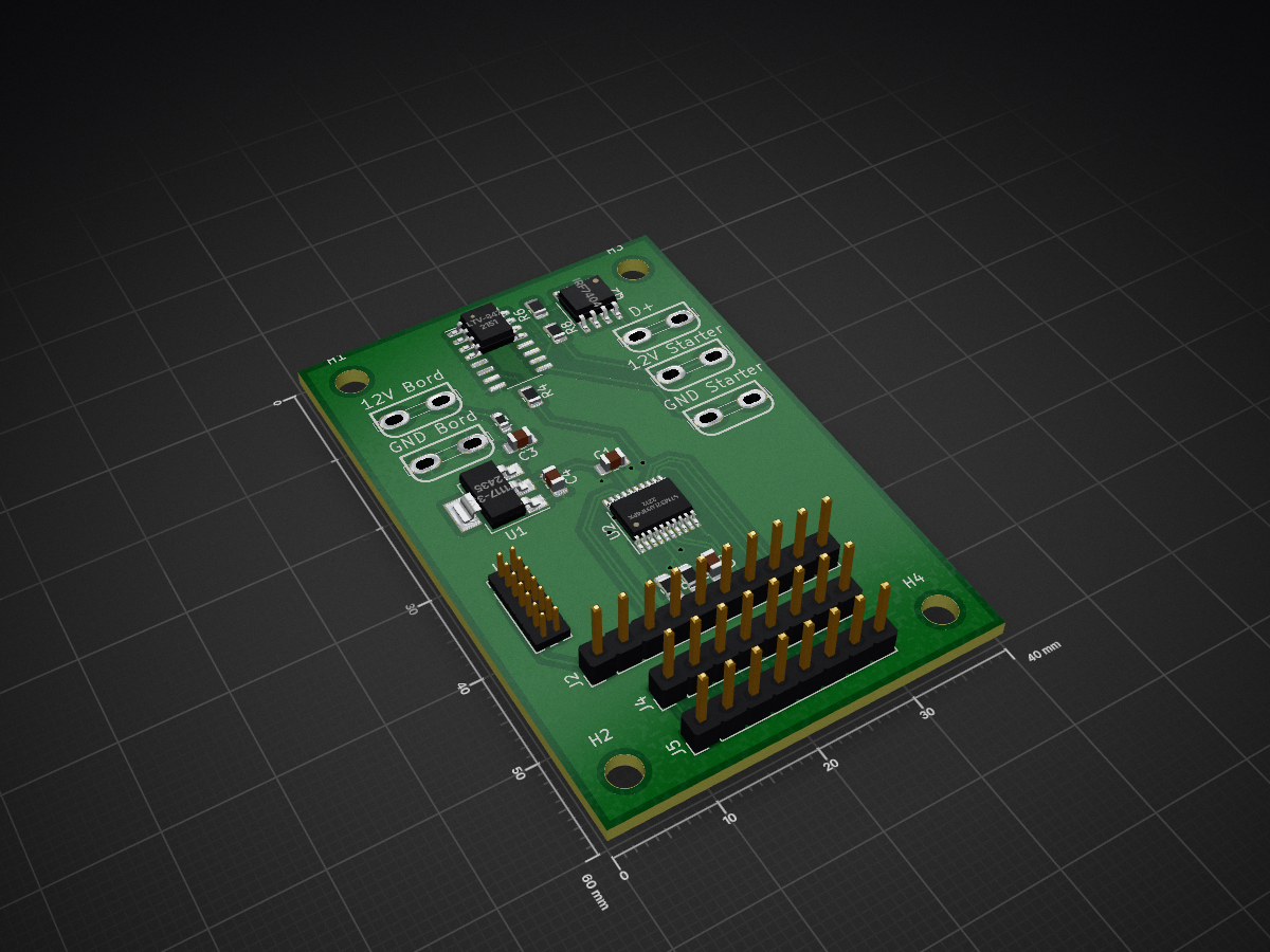
 alexbrickwedde/DplusSim
DplusSim is an open-source printed circuit board by alexbrickwedde, from the alexbrickwedde/DplusSim repository on GitHub. It is a 2-layer board of 40 × 60 mm with 27 parts on 31 nets, routed with 188 tracks and 12 vias.
It is built around the LTV-847. Its parts include 9 connectors, 5 resistors, 4 capacitors, 3 ICs and 1 transistor. It belongs with the STM32 boards of this library.
| Qty | Value | Footprint | References |
|---|---|---|---|
| 4 | MountingHole | MountingHole:MountingHole_3.2mm_M3_DIN965 | H1, H2, H3, H4 |
| 3 | C | Capacitor_SMD:C_0805_2012Metric_Pad1.15x1.40mm_HandSolder | C2, C3, C4 |
| 3 | R | Resistor_SMD:R_0805_2012Metric | R4, R6, R8 |
| 2 | Conn_01x08 | Connector_PinHeader_2.54mm:PinHeader_1x08_P2.54mm_Vertical | J4, J5 |
| 2 | R | Resistor_SMD:R_0805_2012Metric_Pad1.15x1.40mm_HandSolder | R1, R2 |
| 1 | 100n | Capacitor_SMD:C_0805_2012Metric_Pad1.15x1.40mm_HandSolder | C1 |
| 1 | 12V Bord | MyComponents:FASTON-6_3mm | J7 |
| 1 | 12V Starter | MyComponents:FASTON-6_3mm | J6 |
| 1 | Conn_01x10 | Connector_PinHeader_2.54mm:PinHeader_1x10_P2.54mm_Vertical | J2 |
| 1 | Conn_02x07_Odd_Even | Connector_PinHeader_1.27mm:PinHeader_2x07_P1.27mm_Vertical | J1 |
| 1 | D+ | MyComponents:FASTON-6_3mm | J11 |
| 1 | GND Bord | MyComponents:FASTON-6_3mm | J8 |
| 1 | GND Starter | MyComponents:FASTON-6_3mm | J3 |
| 1 | IRF7404 | Package_SO:SOIC-8_3.9x4.9mm_P1.27mm | Q2 |
| 1 | LT1117-3.3 | Package_TO_SOT_SMD:SOT-223 | U1 |
| 1 | LTV-847 | MyComponents:SO-16_3.9x9.9mm_P1.27mm | U5 |
| 1 | Polyfuse | Resistor_SMD:R_0603_1608Metric_Pad1.05x0.95mm_HandSolder | F1 |
| 1 | STM32L031F4Px | Package_SO:TSSOP-20_4.4x6.5mm_P0.65mm | U2 |
tnn85/MPCNC-Nano-Estlcam-Shield
Ein CNC Shield für die MPCNC in Verwendung mit Estlcam

ftl/atu100wifi
A wifi adapter device for David Fainitski's ATU-100 antenna tuner (https://github.com/Dfinitski/N7DDC-ATU-100-mini-and-extended-boards)

pstimpel/waveformgenerator
A waveform generator based on XR2206 and Arduino


411568/Atmega8_FM_radio
Simple FM radio based on Atmega8 and TEA5767 module

JhonVelasquez/Embedded_system_Synchronize_Plant
Project of a embedded system that synchronizes signals in a plant. There is electronic (PCB) and software design (FreeRTOS for STM32F7).

It measures 40 × 60 mm and has 2 copper layers, 1.6 mm thick.
27 parts, built around the LTV-847. The full list of its parts is on this page, with links to each part's symbol and footprint where PCBKit's library has them.
From the alexbrickwedde/DplusSim repository on GitHub, at the commit this page was made from: the board is DplusSim.kicad_pcb. PCBKit opens the board in the browser, with nothing to install.
Its repository states no licence, so its author keeps all rights: ask alexbrickwedde before reusing the design.