2 layers109 × 71 mm

 gmoccapy/T4-MFA9
This is a color MFA designed to be used in a Volkswagen T4 Van
BrakeOutBoard is an open-source printed circuit board by gmoccapy, from the gmoccapy/T4-MFA repository on GitHub. It is a 2-layer board of 63 × 80 mm with 65 parts on 93 nets, routed with 675 tracks and 10 vias.
It is built around the SN65HVD230DR, LTV-847 and EL817(B)-F, with the S3MB, K15 and K31 among its other parts. Its parts include 18 resistors, 6 ICs, 3 switches, 2 capacitors and 2 diodes.


T4-MFA is a projekt to customize the Dash Board from an Volkswagen T4 Van with a color MFA (Multi Function Diaplay)
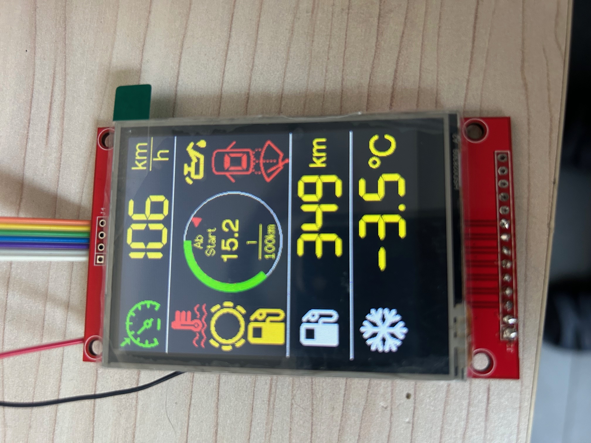
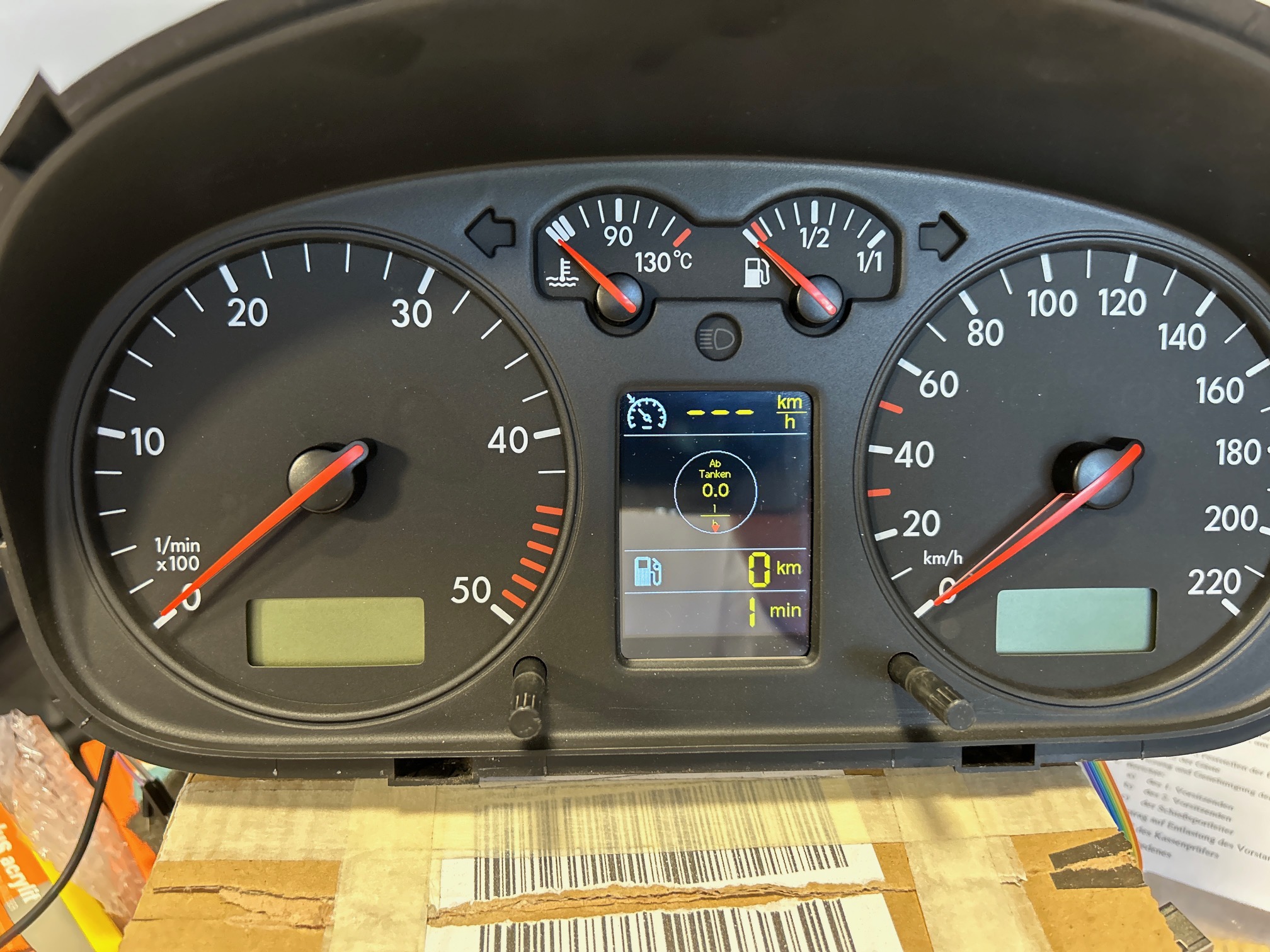
It is based on a ESP32S-Dev Kit C V4 with 512 kB SRAM and 4 MB Flash The used display is an 3,5 Inch RPI Display with 480x320 Pixel The connections from the display need to be modified The CAN connections are done with a WCMCU-230 Modul (R2 has to be removed) Power Control is solved with a 12V USB Car Adapter (the mainboard from the adapter has been used) The connections are done to a self desgned brake out board Some soldering on the Dash Board Instrument has to be done
The fixture of the display has been solved with a 3d printed part.
Please take care to use ARDUINO IDE 2.XX to programm the ESP You will need to use following libraries
Feel free to submit improvements
Electronics and Software Code may be buggy. If you use the code or the hardware mentioned in this repository, you are responsible to check against you local law. I designed this for my own use. I assume no liability for damages resulting from the use of my software or hardware design.
| Qty | Value | Footprint | References |
|---|---|---|---|
| 4 | 10kΩ | PCM_JLCPCB:R_0603 | R1, R14, R15, R16 |
| 4 | MountingHole_3.2mm_M3 | MountingHole:MountingHole_3.2mm_M3 | Hole_1, Hole_2, Hole_3, Hole_4 |
| 3 | 10kΩ | PCM_JLCPCB:R_0603x4 | R9, R10, R13 |
| 3 | 4.7kΩ | PCM_JLCPCB:R_0603x4 | R7, R8, R11 |
| 3 | LTV-847 | Package_DIP:DIP-16_W7.62mm | U1, U2, U3 |
| 2 | 100kΩ | PCM_JLCPCB:R_0603 | R3, R5 |
| 2 | 100nF | PCM_JLCPCB:C_0402 | C1, C2 |
| 2 | 4,7k | PCM_JLCPCB:R_0603 | R17, R18 |
| 2 | Conn_01x19_Socket | Connector_PinSocket_2.54mm:PinSocket_1x19_P2.54mm_Vertical | J1, J2 |
| 2 | S3MB | PCM_JLCPCB:D_SMB | D1, D2 |
| 1 | 220kΩ | PCM_JLCPCB:R_0603 | R2 |
| 1 | 220Ω | PCM_JLCPCB:R_0603 | R6 |
| 1 | 33kΩ | PCM_JLCPCB:R_0603 | R4 |
| 1 | 4.7kΩ | PCM_JLCPCB:R_0603 | R12 |
| 1 | BME280_conn | Connector_PinSocket_2.54mm:PinSocket_1x04_P2.54mm_Vertical | BME_280 |
| 1 | BrakeFluid | Connector_Wire:SolderWire-0.5sqmm_1x01_D0.9mm_OD2.1mm | BF |
| 1 | BrakePads | Connector_Wire:SolderWire-0.5sqmm_1x01_D0.9mm_OD2.1mm | BP |
| 1 | Can_H | Connector_Wire:SolderWire-0.5sqmm_1x01_D0.9mm_OD2.1mm | CAN_H |
| 1 | Can_L | Connector_Wire:SolderWire-0.5sqmm_1x01_D0.9mm_OD2.1mm | CAN_L |
| 1 | Coolant | Connector_Wire:SolderWire-0.5sqmm_1x01_D0.9mm_OD2.1mm | Cool |
| 1 | Door_R | Connector_Wire:SolderWire-0.5sqmm_1x01_D0.9mm_OD2.1mm | RD |
| 1 | Door_S | Connector_Wire:SolderWire-0.5sqmm_1x01_D0.9mm_OD2.1mm | SD |
| 1 | EL817(B)-F | JLCPCB:DIP-4_L6.5-W4.6-P2.54-LS7.6-BL-1 | U4 |
| 1 | GPS Modul expansion port | Connector_PinSocket_2.54mm:PinSocket_1x04_P2.54mm_Vertical | GPS |
| 1 | K15 | Connector_Wire:SolderWire-0.5sqmm_1x01_D0.9mm_OD2.1mm | K15 |
| 1 | K30 | Connector_Wire:SolderWire-0.5sqmm_1x01_D0.9mm_OD2.1mm | K30 |
| 1 | K31 | Connector_Wire:SolderWire-0.5sqmm_1x01_D0.9mm_OD2.1mm | K3 |
| 1 | LBSS84LT1G | PCM_JLCPCB:Q_SOT-23 | Q1 |
| 1 | MCP23017_ML | Package_DFN_QFN:QFN-28-1EP_6x6mm_P0.65mm_EP4.25x4.25mm | U6 |
| 1 | MMDT3904 | Package_TO_SOT_SMD:SOT-363_SC-70-6 | Q2 |
| 1 | Memory | Connector_Wire:SolderWire-0.5sqmm_1x01_D0.9mm_OD2.1mm | MEM1 |
| 1 | Mode | Connector_Wire:SolderWire-0.5sqmm_1x01_D0.9mm_OD2.1mm | MODE1 |
| 1 | MotorCap | Connector_Wire:SolderWire-0.5sqmm_1x01_D0.9mm_OD2.1mm | MC |
| 1 | O_Lev_LED | Connector_Wire:SolderWire-0.5sqmm_1x01_D0.9mm_OD2.1mm | OL_LED |
| 1 | OilPresure | Connector_Wire:SolderWire-0.5sqmm_1x01_D0.9mm_OD2.1mm | OP |
| 1 | Reset | Connector_Wire:SolderWire-0.5sqmm_1x01_D0.9mm_OD2.1mm | RESET1 |
| 1 | SN65HVD230DR | PCM_JLCPCB:SOIC-8_L4.9-W3.9-P1.27-LS6.0-BL | U5 |
| 1 | TFT_5V | Connector_Wire:SolderWire-0.5sqmm_1x01_D0.9mm_OD2.1mm | 5V |
| 1 | TFT_CS | Connector_Wire:SolderWire-0.5sqmm_1x01_D0.9mm_OD2.1mm | CS |
| 1 | TFT_DC | Connector_Wire:SolderWire-0.5sqmm_1x01_D0.9mm_OD2.1mm | DC |
| 1 | TFT_GND | Connector_Wire:SolderWire-0.5sqmm_1x01_D0.9mm_OD2.1mm | GND |
| 1 | TFT_MOSI | Connector_Wire:SolderWire-0.5sqmm_1x01_D0.9mm_OD2.1mm | MOSi |
| 1 | TFT_RST | Connector_Wire:SolderWire-0.5sqmm_1x01_D0.9mm_OD2.1mm | RST |
| 1 | TFT_SLK | Connector_Wire:SolderWire-0.5sqmm_1x01_D0.9mm_OD2.1mm | SLK |
| 1 | To USB converter | Custom:PHOENIX_1729128_2x2,54 | USB_OUT1 |
| 1 | Trunk | Connector_Wire:SolderWire-0.5sqmm_1x01_D0.9mm_OD2.1mm | TR |
| 1 | WhiperWater | Connector_Wire:SolderWire-0.5sqmm_1x01_D0.9mm_OD2.1mm | WW |
| 1 | oilSensor | Connector_Wire:SolderWire-0.5sqmm_1x01_D0.9mm_OD2.1mm | OS |

markstory/ursa-minor-keyboard
Design and schematics for the ursaminor keyboard


alexBinos/Macropad
A 5x4 key macropad with rotary encoder, OLED display and per-key RGB lighting

It measures 63 × 80 mm and has 2 copper layers, 1.6 mm thick.
65 parts, built around the SN65HVD230DR, LTV-847, EL817(B)-F and S3MB. The full list of its parts is on this page, with links to each part's symbol and footprint where PCBKit's library has them.
From the gmoccapy/T4-MFA repository on GitHub, at the commit this page was made from: the board is Hardware/KICAD_MFA_V5/BrakeOutBoard.kicad_pcb and its schematic Hardware/KICAD_MFA_V5/BME_280.kicad_sch. PCBKit opens the board in the browser, with nothing to install.
Its repository states no licence, so its author keeps all rights: ask gmoccapy before reusing the design.