
2 layers50 × 100 mm
Corrector de postura
agustin-arg/Posture
Dispositivo electrónico de corrección de postura corporal
23 parts5

 AlexanderBelchev/ESP32_Console
Turns the ESP32 into a language learning console, specifically for Japanese.
ESP Console is an open-source printed circuit board by AlexanderBelchev, from the AlexanderBelchev/ESP32_Console repository on GitHub, published under the GPL-3.0 licence. It is a 2-layer board of 89 × 115 mm with 13 parts on 47 nets, routed with 163 tracks and 20 vias.
It is built around the NODEMCU-32SLUA. Its parts include 4 resistors and 4 switches. It belongs with the ESP8266 boards of this library.
Following the official documentation from Espressif, you have to setup the standard toolchain for your system:
Linux/MacOS
Windows
After following the documentation you should have the standard toolchain setup.
Now you can clone the repository. Once inside it, run the command
. $HOME/esp/esp-idf/export.sh
or for Fish
. $HOME/esp/esp-idf/export.fish
This will setup the ESP-IDF environment for the project.
Inside the cloned repository should be a directory called SD_CARD_FILES.
Copy its contents to a Micro SD Card and format the card to the FAT32 Format
After inserting the card into the Micro SD Card Reader, you can build and flash the project to the ESP32
This is done by performing the following command inside the cloned repository.
idf.py build flash monitor
This will
As I was not developing this on Windows, I don't know how the setup would go for it.
The project was developed as a final assigment for high school. It utilizes the ESP32 to make a console-like game for learning Japanese Kanji. It consists of multiple components:
The board is two sided THT. Each component is labeled where it's supposed to be soldered on the board.
The clean board looks like this
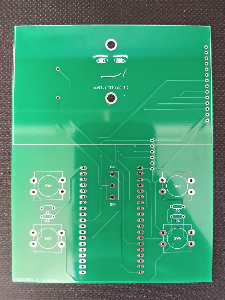
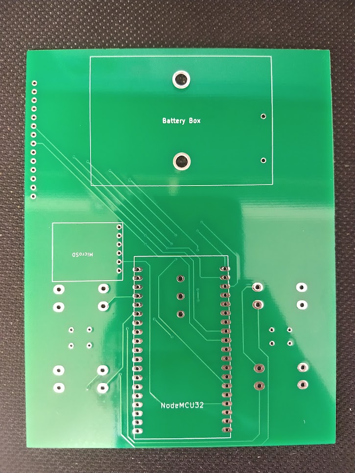
When attaching the components you have to match their orientation with the text on the silkscreen.
The populated PCB should look like this
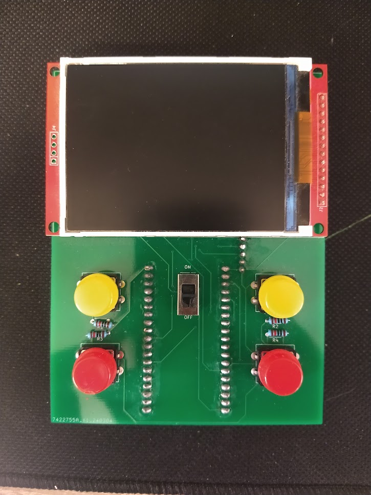
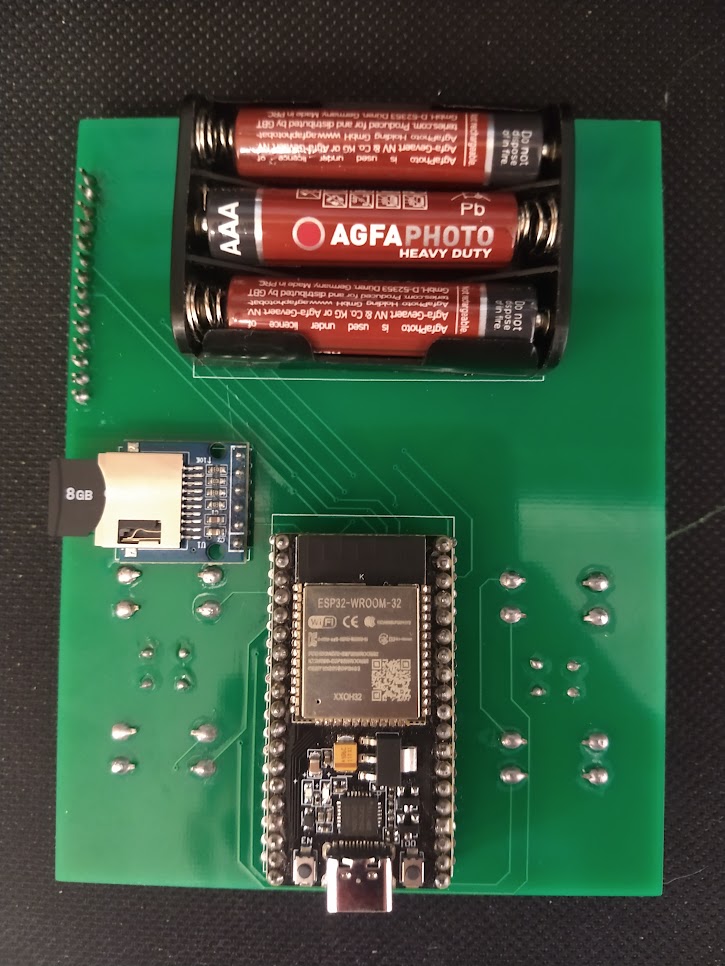
When the console is turned on by the switch in the middle, it will light up and the main menu will show up.
It displays the Highest achieved score that is saved to the Micro SD Card and also a choice to start a game.
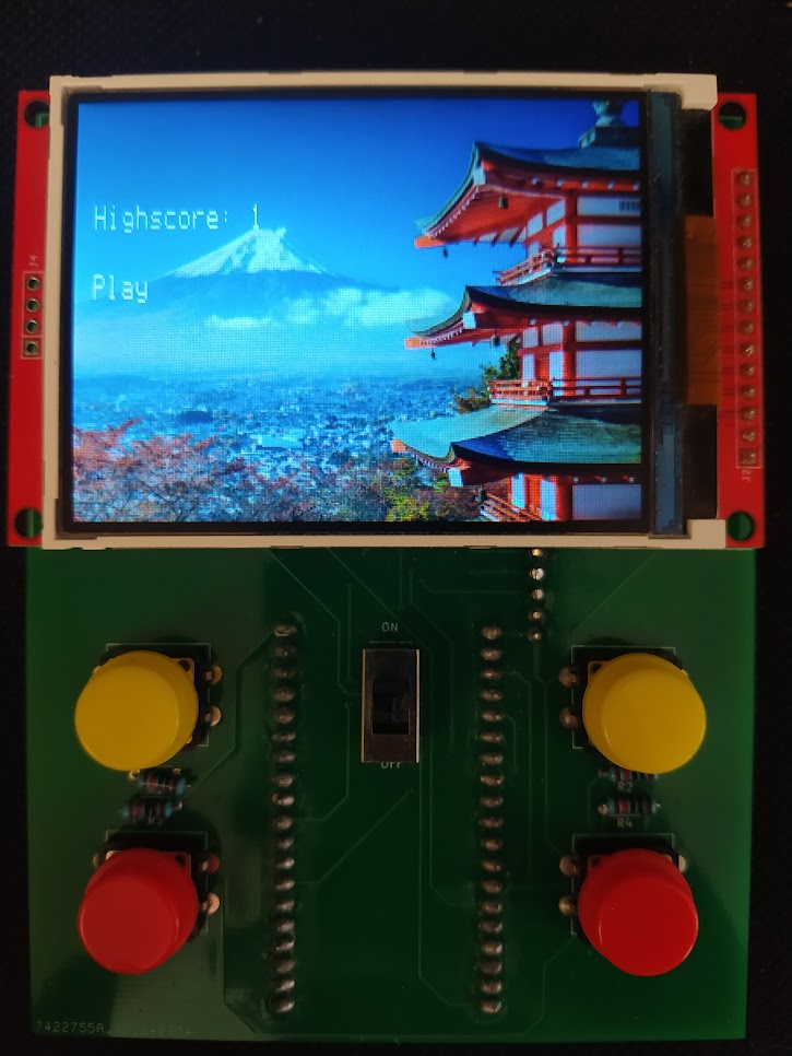
When you press the corresponding button to the play option a new game will begin.
A question will be generated and the answers selectedd. They will either ask for a
translation of the kanji displayed or for a reading in japanese.
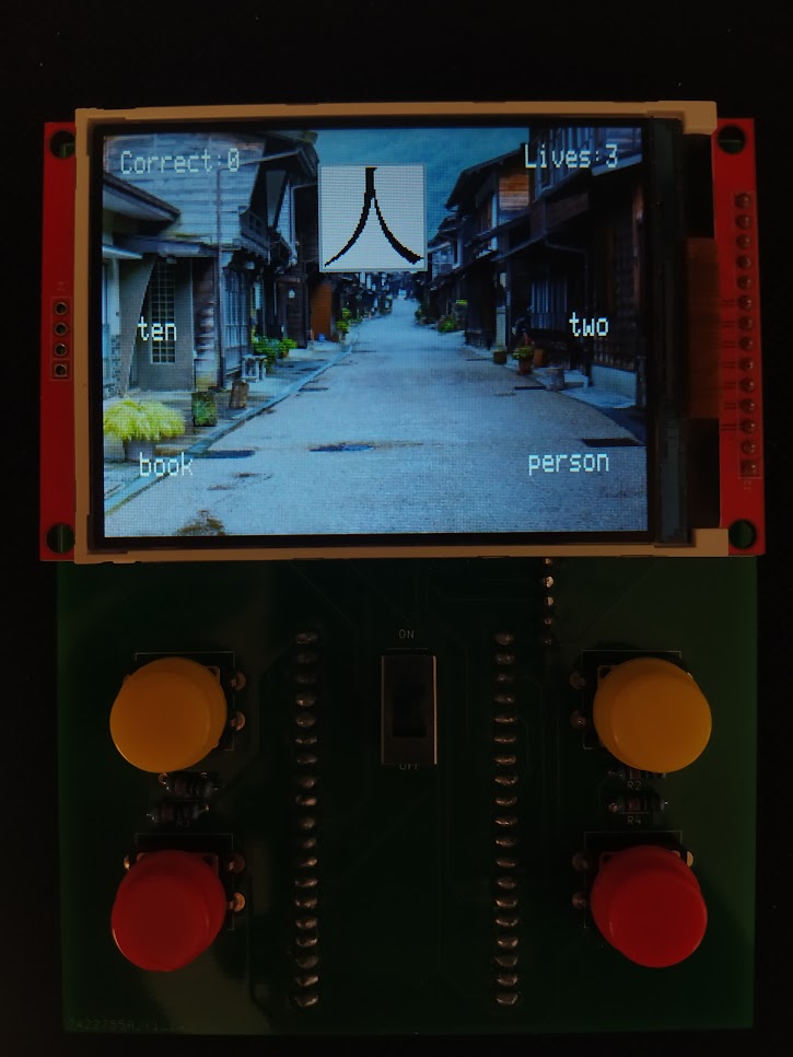
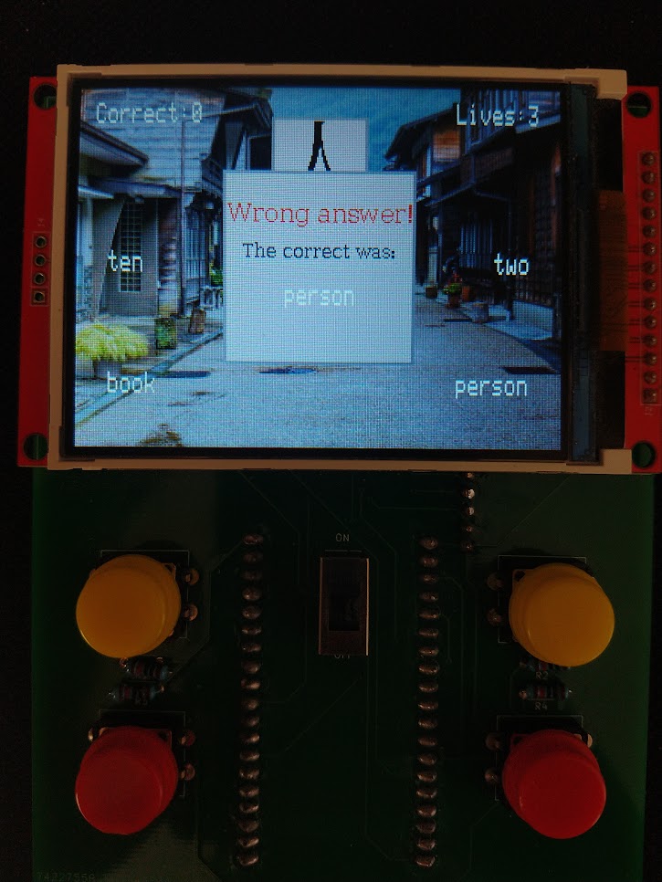
If the chosen answer is wrong the game will deduct one life point and will display the
correct answer for the question.
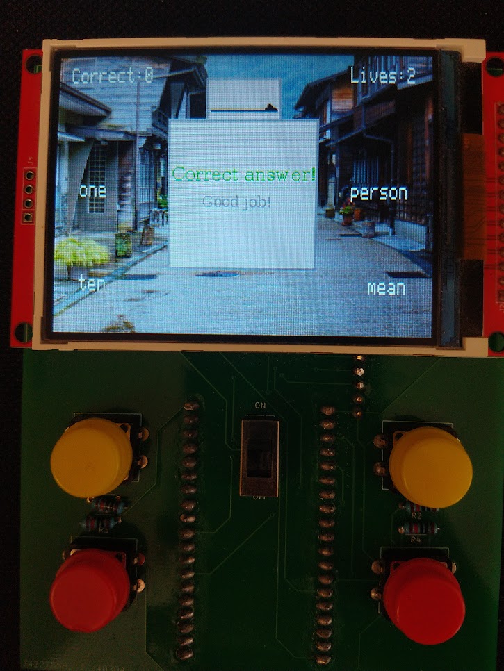
Otherwise if the chosen aswer is correct, the game will give 1 point and notify the player
that the chose answer has been correct.
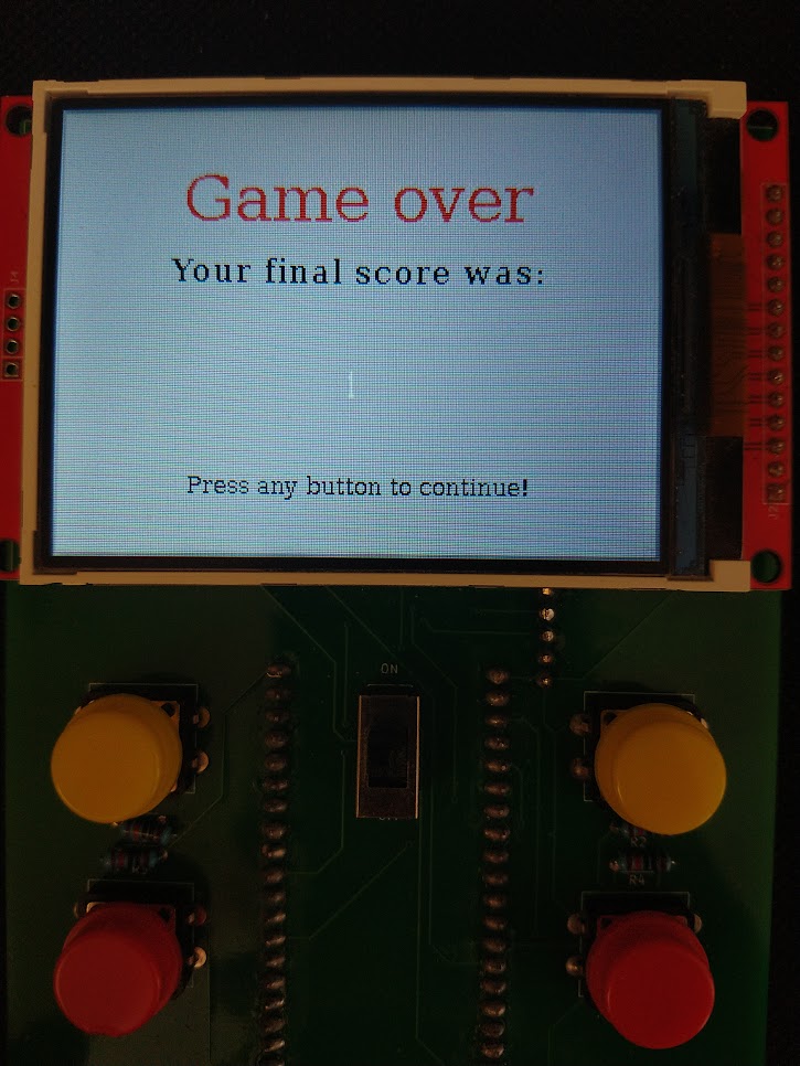
The game will end once the player has ran out of lives, there is no way to end a game without
losing unless you power off the console. At the end of a game, the player will be notified
about the score they managed to get. If the score is more than the recorded high score, it will
be saved as the new highest score.
As this was the first time I ever made something involving a Custom PCB and so many components, I have missed to think about certain things that could prove beneficial for future projects.
For a first time design I feel like this one is OK, but for future projects the design should incorporate less prototyping boards and more individual components, like SMD components. These may require more complicated soldering methods but the final product would have a much more professional and clean look.
Major imporvement would be the use of an independent ESP32 chip that has been flashed with the project.
Another big improvement would come from the TFT display. Instead of using one with a board and pins, an alternative variant that utilises a connector would be better in terms of how thin the console could be.
This was also my first time programming on an ESP32 and ESP-IDF, so a lot was figured out through the examples given by Espressif, but the code was not well suited for this project.
The most improvement that could be done is in the rendering, because the current rendering method is so slow that the FPS is lower than 1, but it can most certainly be at least as good as 10FPS.
Mounting holes designed into the PCB could allow for a case to be made for the console, giving it a more solid look and making it a lot more comfortable and safer than the current one, where you hold the PCB and have to take care of what touches the board.
| Qty | Value | Footprint | References |
|---|---|---|---|
| 4 | R_US | Resistor_THT:R_Axial_DIN0204_L3.6mm_D1.6mm_P5.08mm_Horizontal | R1, R2, R3, R4 |
| 4 | SW_Push_Open_Dual | Button_Switch_THT:SW_PUSH-12mm_Wuerth-430476085716 | SW1, SW2, SW3, SW4 |
| 1 | 2479 | other:3xAAA battery box 2479 | Battery Box |
| 1 | NODEMCU32S | other:NODEMCU32S | NodeMCU32 |
| 1 | ~ | other:SW_1P2T | SW_1P2T1 |
| 1 | ~ | other:3.2inch SPI Module MSP3218 | ILI9341 TFT LCD 3.2 |
| 1 | ~ | other:Micro SD reader module | MicroSD |
It measures 89 × 115 mm and has 2 copper layers, 1.6 mm thick.
13 parts, built around the NODEMCU-32SLUA. The full list of its parts is on this page, with links to each part's symbol and footprint where PCBKit's library has them.
From the AlexanderBelchev/ESP32_Console repository on GitHub, at the commit this page was made from: the board is PCB_DESIGN/ESP_Console/ESP_Console.kicad_pcb and its schematic PCB_DESIGN/ESP_Console/ESP_Console.kicad_sch. PCBKit opens the board in the browser, with nothing to install.
Its repository publishes it under the GPL-3.0 licence: you may reuse it on that licence's terms (keep the author's notice, and for a copyleft licence share your changes alike).
agustin-arg/Posture
Dispositivo electrónico de corrección de postura corporal

unla-investigacion-desarrollo/ecosistema-iot
Antes de desarrollar el sistema final, realizamos una etapa de exploración donde investigamos y experimentamos con las siguientes tecnologías:


bytecod3/lora-life-jacket
Electronic device for life jackets with LORA data transmission

hopkinskong/eie553-iot-hardware
ESP32 IOT Smart Lock Device Hardware Schematic and PCB used in the course "EIE553 Security in Data Communication".

2026MakerClub/PCB
projects with pcb, custom and commonly used schemes, footprints...etc.

ANTzacalie/termo-pro-esp32
Full-featured smart thermostat built on the ESP32 platform.
