

2 layers64.1 × 98.3 mm
Lora life jacket
bytecod3/lora-life-jacket
Electronic device for life jackets with LORA data transmission
17 parts2Apache-2.0
 bytecod3/ear-tag1
Ear tag with LORA
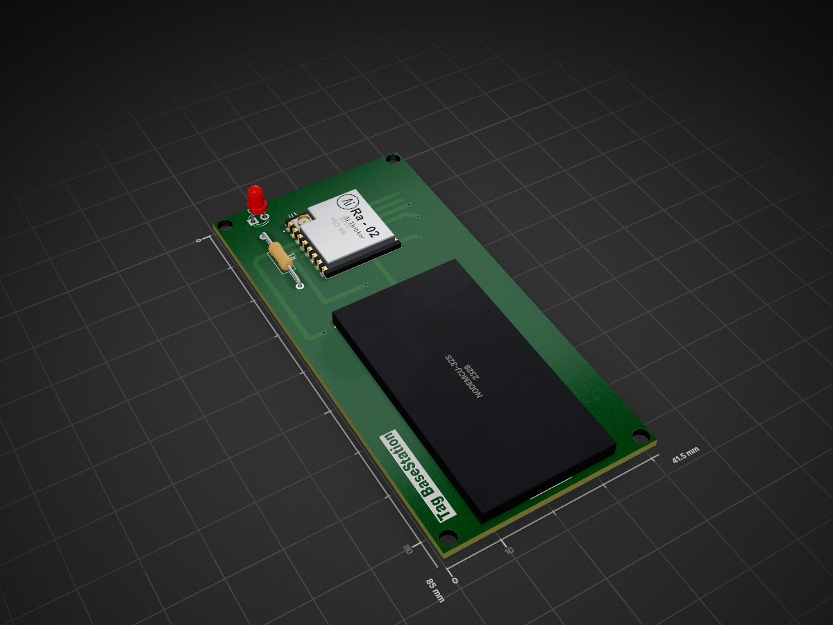
Base station is an open-source printed circuit board by bytecod3, from the bytecod3/ear-tag repository on GitHub, published under the MIT licence. It is a 2-layer board of 41.5 × 85 mm with 4 parts on 43 nets, routed with 95 tracks and 12 vias.
It is built around the NODEMCU-32SLUA and RA-01H. Its parts include 2 ICs, 1 resistor and 1 diode. It belongs with the ESP8266 boards of this library.
Ear tag with LORA
This proejct implements a catle ear tag using LORA technology. The purpose of the tag is to monitor location and activity of the cattle. It is tailored to open ranch setups where the cattle have a huge chunk of land to graze.
This ear tag also monitors the activity level of the cattle and uses a custom algrithm to detect shcok and abnormal vibrations to tell whether the animal fell, is still lying down etc.
The device reads accelerations from an accelerometer sensor and does data processing to translate them into useful data like shock and activity levels. Using a GPS, we can monitor the real-time location of the animal.
This data is transmitted to a base station via a LORA gateway and visualized on the farmer's device, either phone and/or desktop setup.
MPU6050 measures acceleration using its on-chip accelerometer with four programmable full scale ranges of ±2g, ±4g, ±8g and ±16g that can be set by the user.The X, Y and Z are relative to how the chip sits on the module as shown to the right and will ultimately be dependent on the orientation of the module on the device.
MPU6050 measures rotation using its on-chip gyroscope with four programmable full scale ranges of ±250°/s, ±500°/s, ±1000°/s and ±2000°/s that can be set by the user. The axis of rotation are relative the the X,Y and Z shown to the right.
The module uses I2C interface for communications with MCU.It supports two different I2C addresses;0x68 and 0x69.That allows two devices to be used on the same bus or in case there is an address conflict with another device on the bus. The AD0 pin determines the I2C address to use.This pin has built in 4.7k pull-down resistor on module.if the pin is left unconnected,the line will be pulled low and the default I2C address will be 0X68.To select 0x69, connect the ADO pin to 3.3V. The SCL and SDA pins connect to A5 and A4 pins in analog input pins on the arduino board. The Auxiliary I2C address with pins labeled EDA and ECL are an I2C bus controlled by the MPU-9250 so that it can communicate directly with other sensors so that it can get additional information for its internal computations.
Acceleration is read from all axes(x, y, z). The read values are then used to calculate the pitch and roll angles as shown below.
pitch = 180 * atan2(accelX, sqrt(accelY*accelY + accelZ*accelZ))/PI roll = 180 * atan2(accelY,sqrt(accelX*accelX + accelZ*accelZ))/PIAfter obtaining MPU6050 accelerometer and gyroscope readings, addressing sensor drift, noise, and measurement errors is essential for accurate motion tracking and orientation estimation. [1]
Animal exhibit distinct diurnal patterns depending on the time of day[2]. This means that in the morning and evening they show high activity but during nightime they are ruminating and therefore low activiy. To detect the shocks, a High pass filter(HPF) is used to discard all data/noise below a given cutoff frequency.
This ear tag uses a simple complemetary filter to do the data cleanup especially when calulating the pitch and roll angles. The formula is shown below:
angle = alpha * (accelerometer_value + gyroscope_value * dt) + (1 - alpha)* accelerometer_valueThe graph shows the results obtained from applying this complementary filter:
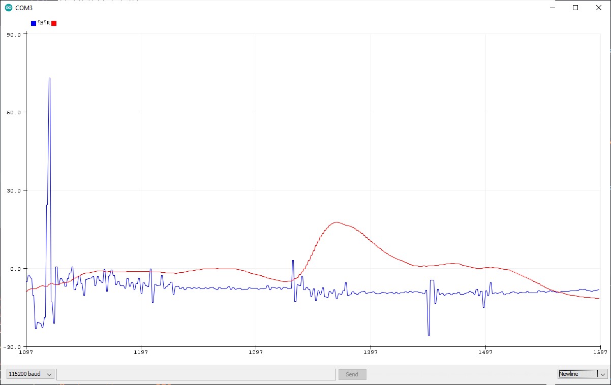
The red line shows the filtered pitch angle while the blue line shows the raw pitch angle.
The moving average filter is used to smooth out acceleration values to remove high frequency noise. It averages the last N values and returns a cleaner value. This filter is used when we do not have big memory constraints and at the same time we need to implement basic filtering.
/* pseudo code */

create a buffer
read sensor
store the previous N values
calculate the average of the values
return the average
The acceleration values are prone to high frequency noise therefore the average filter was applied to them. The image below shows the result of filtering the x acceration:
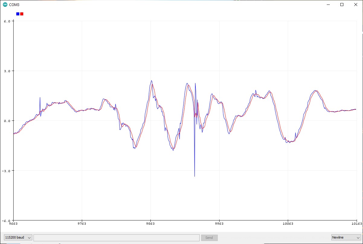
The blue line shows the raw unfiltered value. Red line shows the filterd value. As it can be seen, the moving average filter works as expected, removing high frequency noise from the acceleration value.
In case the animal falls, we can use the MPU6050 to detect the shock and apply corrective measures. The accelerometer used is configured to measure up to (+/-)16g range.
To be able to register sudden animal activity, we have to keep track of the resultant acceleration, also called the magnitude of acceleration. The graph below shows the valeus of the raw magnitude of acceleration(using raw unfiltered values):
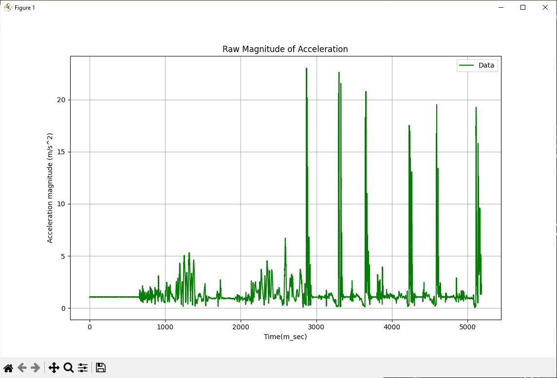
The sharp spikes show the acceleration when the device is dropped from about 40 cm high. It can clearly be seen that the magnitude of acceleration is high when this occurs.
This next figure shows the resultant acceleration using raw and filtered acceleration values, combined into a single plot.
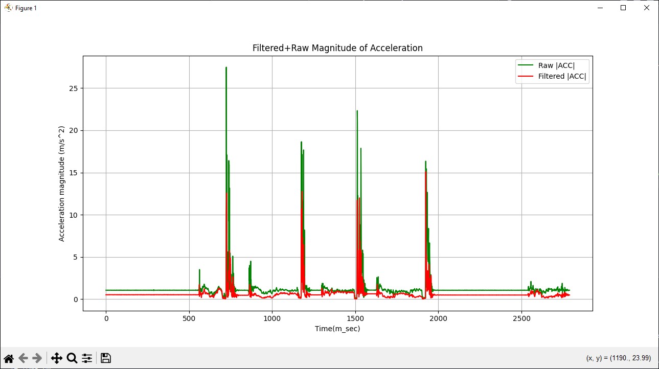
The red line shows the cleaner values obtained from the accelerometer.
By monitoring the value of this acceleration, we can be able to set a threshold that we then check to determine if there is a sudden upsurge of activity.
To track the animal in real time we emply a NEO6M GPS module that read the GPS location data. The data read from GPS is:
This data is then packaged into a packet to make it easier for transmission. The GPS is read at a frequency defined by the DATA_UPDATE frequency value.
| Field Name | Data Type | Description |
|---|---|---|
| tag_id | uint32_t | Unique identifier for the tag |
| mode | uint8_t | 0 = Operational, 1 = Simulation |
| day | uint8_t | Day (1-31) |
| month | uint8_t | Month (1-12) |
| year | uint16_t | Year (e.g., 2025) |
| hour | uint8_t | Hour (0-23) |
| minute | uint8_t | Minute (0-59) |
| second | uint8_t | Second (0-59) |
| latitude | float | GPS latitude in degrees |
| longitude | float | GPS longitude in degrees |
| geo_fence_proximity | uint8_t | Proximity to geofence (0-100%) |
| acceleration_x | float | X-axis acceleration (m/s²) |
| acceleration_y | float | Y-axis acceleration (m/s²) |
| acceleration_z | float | Z-axis acceleration (m/s²) |
| acceleration_magnitude | float | √(x² + y² + z²) (m/s²) |
The device is configured to search for available networks and connect to them automatically. To do this, we implement a WIFI provisioning scheme that allows you to connect to the network you desire.
Follow the steps below to connect:
192.168.4.1This section defiens the steps to connect tot the server. The server is built using with NodeJS and runs a MongoDB database.
web app folder in terminalnodemon server.jsipconfigNow to make the ear-tag-device connect to the server, make sure the PC amd the ear tag are on the same network using the WIFI connection procedures listed above.
Since this is not a production environment and we have dynamic IP addresses, we need to update our server IP address in the Ear-tag firmware. Locate the server line below in the firmware and change to:
const char* server_url = "http://YOUR_IP_ADDRESS:3000/api/location";Replace with your IP address.
Upload the code the device and restart.
The PCBs are designed using EasyEDA Pro. Please download EasyEDA Pro here -> https://easyeda.com/page/download
To open the flowcharts and diagrams, download draw.io app here -> https://github.com/jgraph/drawio-desktop/releases/tag/v25.0.2 Choose the WindowsInstaller version
[1] [2] text
| Qty | Value | Footprint | References |
|---|---|---|---|
| 1 | 200R | Resistor_THT:R_Axial_DIN0207_L6.3mm_D2.5mm_P15.24mm_Horizontal | R1 |
| 1 | NODEMCU-32S | NODEMCU-32S:MODULE_NODEMCU-32S | U2 |
| 1 | RA-01H | RA-01H:XCVR_RA-01H | U1 |
| 1 | USER | LED_THT:LED_D3.0mm | D1 |
It measures 41.5 × 85 mm and has 2 copper layers, 1.6 mm thick.
4 parts, built around the NODEMCU-32SLUA and RA-01H. The full list of its parts is on this page, with links to each part's symbol and footprint where PCBKit's library has them.
From the bytecod3/ear-tag repository on GitHub, at the commit this page was made from: the board is hardware/base-station/base-station.kicad_pcb and its schematic hardware/base-station/base-station.kicad_sch. PCBKit opens the board in the browser, with nothing to install.
Its repository publishes it under the MIT licence: you may reuse it on that licence's terms (keep the author's notice, and for a copyleft licence share your changes alike).
bytecod3/lora-life-jacket
Electronic device for life jackets with LORA data transmission

electromotif208/pcb-portfolio
👨💻 Electronics Engineer 📺 YouTube: ELECTROMOTIF 🔧 Tools: KiCad, EasyEDA 📡 Domains: Power Supply, ESP32, IoT, Embedded Hardware

DetectiveMittens/Cooee
An open-source phone that can operate without GSM or LTE coverage. Utilising LoRa modulation and mesh networking to enable long range "off-grid" communication

Tay0710/Design_S1_006
This project integrates hardware, firmware, and design elements to develop a fully functional autonomous 3D mapping drone system.

agustin-arg/Posture
Dispositivo electrónico de corrección de postura corporal

unla-investigacion-desarrollo/ecosistema-iot
Antes de desarrollar el sistema final, realizamos una etapa de exploración donde investigamos y experimentamos con las siguientes tecnologías:


hopkinskong/eie553-iot-hardware
ESP32 IOT Smart Lock Device Hardware Schematic and PCB used in the course "EIE553 Security in Data Communication".