4 layers50.8 × 50.8 mm
 AlanFord/CentralCommand
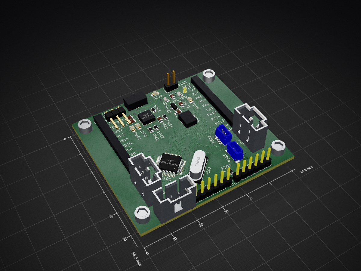
Central Command pcb for the Contextual Electronics class
CentralCommand is an open-source printed circuit board by AlanFord, from the AlanFord/CentralCommand repository on GitHub. It is a 4-layer board of 61.2 × 54.5 mm with 69 parts on 66 nets, routed with 627 tracks and 85 vias.
It is built around the STM32F030C8T6, FT232RQ and MCP1700T-3302E/TT(MS). Its parts include 15 capacitors, 15 resistors, 12 connectors, 6 diodes and 3 ICs. It belongs with the STM32 boards of this library.


Central Command pcb for the Contextual Electronics class
The objective of this portion of the class was to design and build a development board based on the STM32F030 MCU. USB functionality is provided via an FTDI FT232RQ device attached to USART2. An 8Mhz external clock is provided by a crystal. External headers are provided for USART1, I2C2, SPI1, ADC, and a programming connection. I2C1 functionality is provided via two JST SH connectors. One user LED is provided. An on-board reset button will reset the mcu.
The board can be powered either by the USB connection or via an external power supply providing between 3.75 and 6V. The voltage regulator can provide a maximum of 250 mA at 3.3V.
UPDATE: The board should be powered through the external power connection P202 when the board is being programmed. If the board is powered via the USB connector during programming, the trace between the reset button, SW301, and the FTD232RQ USB interface must be cut. Without cutting this trace the mcu reset that occurs during programming will simultaneously reset the FTD232RQ device, momentarily powering down the entire board.
UPDATE #2: The firmware folders and files have been restructured and updated to support the use of the STM32CubeIDE. To use the IDE, simply create a workspace and import this project.
| Qty | Value | Footprint | References |
|---|---|---|---|
| 7 | 0 | Resistors_SMD:R_0805 | R201, R202, R301, R302, R303, R304, R305 |
| 5 | 0.1u | Capacitors_SMD:C_0805 | C203, C204, C205, C206, C301 |
| 3 | 0.1uF | Capacitors_SMD:C_0805 | C104, C105, C106 |
| 3 | 270 | Resistors_SMD:R_0805 | R101, R205, R206 |
| 2 | 10nF | Capacitors_SMD:C_0805 | C107, C201 |
| 2 | 26pF | Capacitors_SMD:C_0805 | C101, C102 |
| 2 | 4.7K | Resistors_SMD:R_0805 | R306, R307 |
| 2 | 40nH | Capacitors_SMD:C_0805 | L101, L201 |
| 2 | D_Schottky_Small | Diodes_SMD:D_0805 | D201, D202 |
| 2 | GPIO1 | Pin_Headers:Pin_Header_Straight_1x12 | P102, P103 |
| 2 | NOPOP | Resistors_SMD:R_0805 | R203, R204 |
| 1 | 1uF | Capacitors_SMD:C_0805 | C108 |
| 1 | 330 | Resistors_SMD:R_0805 | R207 |
| 1 | 4.7u | Capacitors_SMD:C_0805 | C202 |
| 1 | 4.7uF | Capacitors_SMD:C_0805 | C103 |
| 1 | 8Mhz | Crystals:Crystal_HC49-SD_SMD | Y101 |
| 1 | ADC | Pin_Headers:Pin_Header_Straight_1x04 | P106 |
| 1 | BOOT | Pin_Headers:Pin_Header_Straight_1x03 | P304 |
| 1 | FT232RQ | CentralCommand:FT232RQ | IC201 |
| 1 | GRN LED | LEDs:LED_0805 | D203 |
| 1 | I2C | Pin_Headers:Pin_Header_Straight_1x04 | P101 |
| 1 | INPUT | Connectors_JST:JST_SH_BM04B-SRSS-TB_04x1.00mm_Straight | P303 |
| 1 | MCP1700T-3302E/TT | TO_SOT_Packages_SMD:SOT-23 | U201 |
| 1 | OUTPUT | Connectors_JST:JST_SH_BM04B-SRSS-TB_04x1.00mm_Straight | P302 |
| 1 | POWER | Pin_Headers:Pin_Header_Straight_1x02 | P202 |
| 1 | PROGRAM | Pin_Headers:Pin_Header_Straight_1x06 | P301 |
| 1 | PWR LED | LEDs:LED_0805 | D205 |
| 1 | RED LED | LEDs:LED_0805 | D101 |
| 1 | SPI | Pin_Headers:Pin_Header_Straight_1x06 | P105 |
| 1 | STM32F030C8 | Housings_QFP:LQFP-48_7x7mm_Pitch0.5mm | IC101 |
| 1 | SW_Push | CentralCommand:TL3315 | SW301 |
| 1 | USART | Pin_Headers:Pin_Header_Straight_1x04 | P104 |
| 1 | USB_OTG | CentralCommand:10118193 | P201 |
| 1 | V-IN | Measurement_Points:Measurement_Point_Round-SMD-Pad_Small | TP201 |
| 1 | YLW LED | LEDs:LED_0805 | D204 |
The 56 most common of 69 parts.
It measures 61.2 × 54.5 mm and has 4 copper layers, 1.6 mm thick.
69 parts, built around the STM32F030C8T6, FT232RQ and MCP1700T-3302E/TT(MS). The full list of its parts is on this page, with links to each part's symbol and footprint where PCBKit's library has them.
From the AlanFord/CentralCommand repository on GitHub, at the commit this page was made from: the board is Hardware/CentralCommand.kicad_pcb. PCBKit opens the board in the browser, with nothing to install.
Its repository states no licence, so its author keeps all rights: ask AlanFord before reusing the design.

r-pv/rSTM32F030C8T6_ProMiniPlus
An ST development board based on the STM32F030C8T6 MCU compatible with STM32Duino (Arduino).


trope-oshw/anthracite
MIDI-controllable fuzz pedal: open hardware (CERN-OHL-S-2.0), firmware (GPL-3.0-or-later)


rjhsun/stm32f0-devboard
A minimal development board featuring an STM32F030C8T6


khomyakova228-cell/pulse-oximeter
Домашнее задание по курсу «САПР электронных средств» «Проект печатного узла пульсоксиметра в KiCad: оформление по ГОСТ, библиотека компонентов, автоматизация проверки и выпуска» Обозначение документа: БИГЕ.149980.001 Э3