
2 layers16.5 × 12.7 mm
USBCpow
akita11/USBCpow
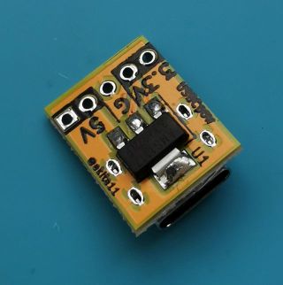
以下、3.3V出力を作る場合の追加部品 - レギュレータLM1117-3.3(または互換品) 1個 - チップコンデンサ 10uF(1608サイズ)/10V以上 2個 ※C1,C2のところに実装
9 parts5MIT

 akita11/USBCpow5
以下、3.3V出力を作る場合の追加部品 - レギュレータLM1117-3.3(または互換品) 1個 - チップコンデンサ 10uF(1608サイズ)/10V以上 2個 ※C1,C2のところに実装
USBCpow6x7 is an open-source printed circuit board by akita11, from the akita11/USBCpow repository on GitHub, published under the MIT licence. It is a 2-layer board of 99.1 × 88.9 mm with 378 parts on 5 nets, routed with 2,646 tracks and 42 vias.
It is built around the LM1117-3.3. Its parts include 168 connectors, 84 capacitors, 84 resistors and 42 ICs.
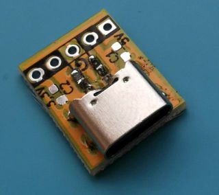
USB Type-Cから5Vを供給するボードです。オプションで3.3Vレギュレータを載せて、3.3Vも出力することができます。
なお実際に供給できる電流は、給電側(USB ACアダプタやモバイルバッテリ)の性能に依存します。また3.3V出力は600mAまでです。
完成品はスイッチサイエンス等で委託販売中です。5V版 / 5V/3.3V版
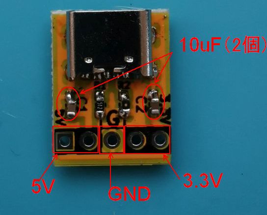
+5V(および+3.3V)、GNDの端子にビニール線やピンヘッダやソケットをとりつけ、回路に電源を供給します。
以下のようにGNDと+5V(または+3.3V)に2ピンのピンヘッダをとりつけることで、ブレッドボードの電源ラインへの給電につかうことができます。


以下のようにUSBコネクタ脇の穴に1ピンのピンヘッダをとりつけることで、ブレッドボードにしっかり固定することができます。


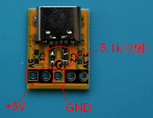
以下、3.3V出力を作る場合の追加部品
Junichi Akita (akita@ifdl.jp, @akita11)
| Qty | Value | Footprint | References |
|---|---|---|---|
| 84 | 5.1k | Resistor_SMD:R_0603_1608Metric_Pad1.05x0.95mm_HandSolder | R1, R1, R1, R1, R1, R1, R1, R1, R1, R1, R1, R1, R1, R1, R1, R1 +68 |
| 84 | Conn_01x01 | Connector_PinHeader_2.54mm:PinHeader_1x01_P2.54mm_Vertical | J2, J2, J2, J2, J2, J2, J2, J2, J2, J2, J2, J2, J2, J2, J2, J2 +68 |
| 42 | 0.1u | Capacitor_SMD:C_0603_1608Metric_Pad1.05x0.95mm_HandSolder | C1, C1, C1, C1, C1, C1, C1, C1, C1, C1, C1, C1, C1, C1, C1, C1 +26 |
| 42 | 10u | Capacitor_SMD:C_0603_1608Metric_Pad1.05x0.95mm_HandSolder | C2, C2, C2, C2, C2, C2, C2, C2, C2, C2, C2, C2, C2, C2, C2, C2 +26 |
| 42 | CON_USB-C-6 | akita:USB-C_6P | CN1, CN1, CN1, CN1, CN1, CN1, CN1, CN1, CN1, CN1, CN1, CN1, CN1, CN1, CN1, CN1 +26 |
| 42 | Conn_01x05 | Connector_PinHeader_2.54mm:PinHeader_1x05_P2.54mm_Vertical | J1, J1, J1, J1, J1, J1, J1, J1, J1, J1, J1, J1, J1, J1, J1, J1 +26 |
| 42 | LM1117-3.3 | Package_TO_SOT_SMD:SOT-223-3_TabPin2 | U1, U1, U1, U1, U1, U1, U1, U1, U1, U1, U1, U1, U1, U1, U1, U1 +26 |
akita11/USBCpow
以下、3.3V出力を作る場合の追加部品 - レギュレータLM1117-3.3(または互換品) 1個 - チップコンデンサ 10uF(1608サイズ)/10V以上 2個 ※C1,C2のところに実装

UtilitechAS/amsreader-firmware
ESP8266 and ESP32 compatible firmware to read, interpret and publish data to MQTT from smart electrical meters, both DLMS and DSMR is supported

karawin/Ka-Radio
A wifi webradio with only low cost boards ESP8266 and VS1053 by Jp Cocatrix


doudar/SmartSpin2k
Transform your spin bike into a Smart Trainer!

plinkysynth/plinky_public
a public release of the plinky sw and hw

eddyem/stm32samples
Code samples and ready projects based on bare-metal STM32


It measures 99.1 × 88.9 mm and has 2 copper layers, 1.6 mm thick.
378 parts, built around the LM1117-3.3. The full list of its parts is on this page, with links to each part's symbol and footprint where PCBKit's library has them.
From the akita11/USBCpow repository on GitHub, at the commit this page was made from: the board is USBCpow6x7.kicad_pcb. PCBKit opens the board in the browser, with nothing to install.
Its repository publishes it under the MIT licence: you may reuse it on that licence's terms (keep the author's notice, and for a copyleft licence share your changes alike).