Skip to the content
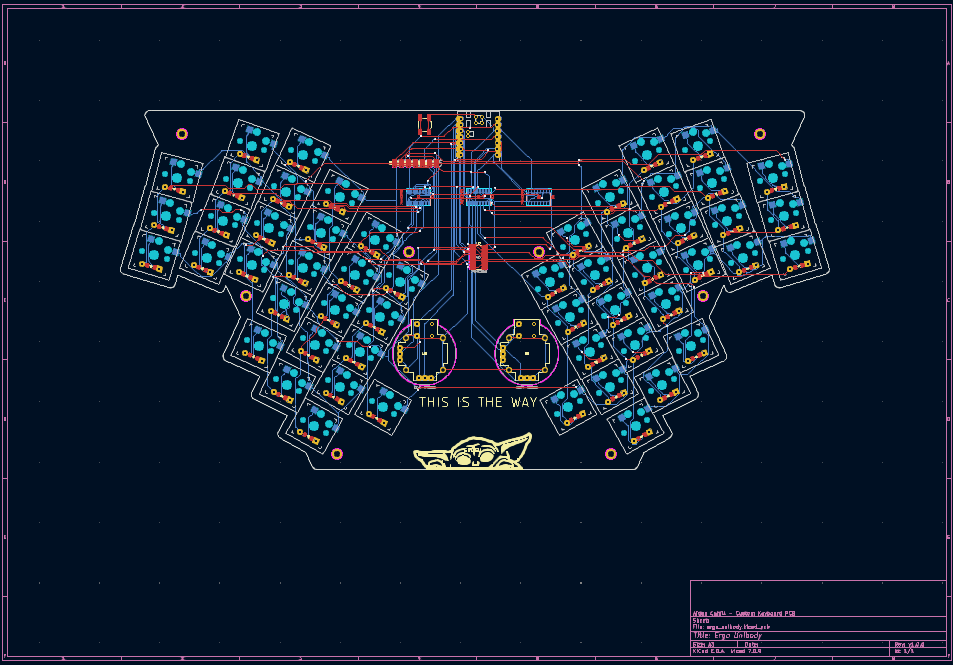
2 layers298.9 × 151.4 mmErgo unibody, the printed circuit board in 3D

A 54-key split ergonomic keyboard with analog joysticks, shift register matrix scanning, and a Seeeduino XIAO nRF52840 BLE microcontroller. Designed from scratch using Ergogen, KiCad, and ZMK firmware.

Size
298.9 × 151.4 mm
Copper layers
2
Thickness
1.6 mm
Parts
132
Nets
105
Pads
904
Tracks, vias
2,287, 84
Routed
Yes
KiCad
KiCad 7 (file 20221018)
Created
30 Mar 2026
Updated
6 Apr 2026

Overview

Ergo unibody is an open-source printed circuit board by aidancahill, from the aidancahill/custom-keyboard repository on GitHub, published under the MIT licence. It is a 2-layer board of 298.9 × 151.4 mm with 132 parts on 105 nets, routed with 2,287 tracks and 84 vias.

It is built around the 74HC595, COM-09032 and 74HC165D. Its parts include 55 switches, 54 diodes, 7 resistors and 7 ICs. It belongs with the keyboards and input boards and the nRF52 and nRF5x boards of this library.

Main components

3

README

README.md

custom-keyboard

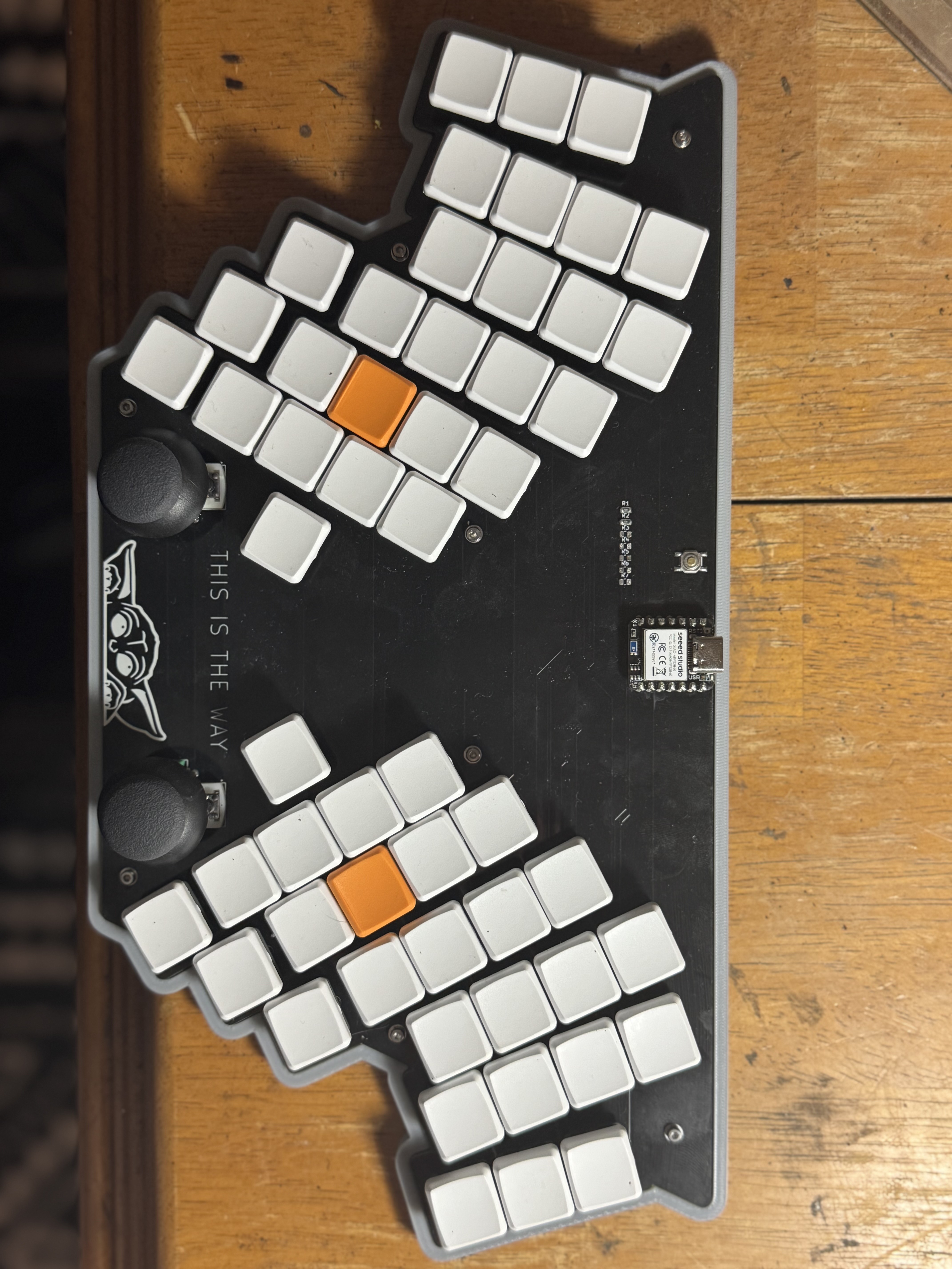
A 54-key split ergonomic keyboard with analog joysticks, shift register matrix scanning, and a Seeeduino XIAO nRF52840 BLE microcontroller. Designed from scratch using Ergogen, KiCad, and ZMK firmware.

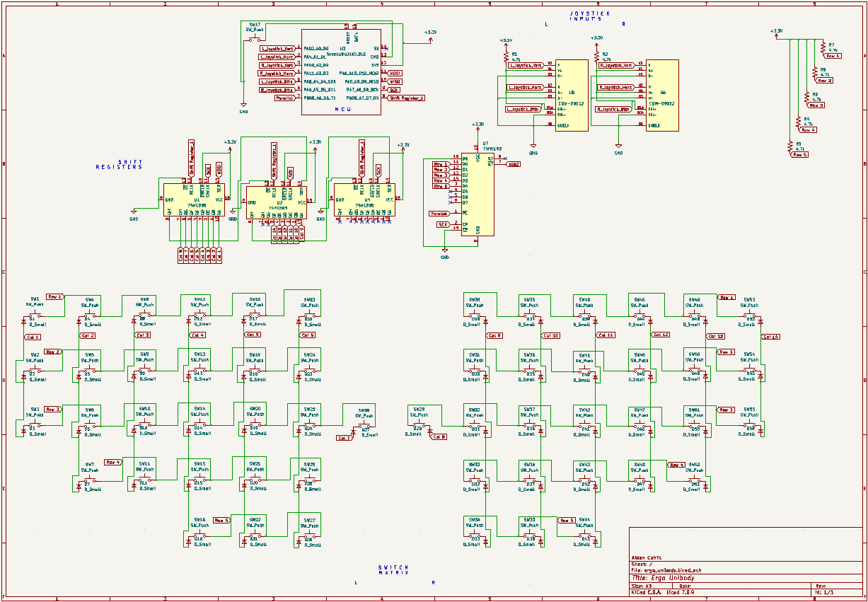
Completed Build PCB Front Schematic

Features

  • 54 Kailh Choc V1 low-profile keys with hotswap sockets
  • Split ergonomic layout with column stagger and splay
  • 2× analog joysticks (mouse movement + scroll)
  • 74HC595 shift registers for column scanning (3× SIPO)
  • 74HC165 shift register for row reading (1× PISO)
  • Seeeduino XIAO nRF52840 BLE MCU
  • 3D printed case with integrated bottom plate and heat-set inserts
  • Custom Grogu silkscreen art

Layout

text
Left half:                              Right half:
+---+---+---+---+---+---+              +---+---+---+---+---+---+
|Esc| 1 | 2 | 3 | 4 | 5 |              | 6 | 7 | 8 | 9 | 0 |Bks|
+---+---+---+---+---+---+              +---+---+---+---+---+---+
|Tab| Q | W | E | R | T |              | Y | U | I | O | P | \ |
+---+---+---+---+---+---+---+      +---+---+---+---+---+---+---+
| ` | A | S | D | F | G |Alt|      |Alt| H | J | K | L | ; | ' |
+---+---+---+---+---+---+---+      +---+---+---+---+---+---+---+
    | Z | X | C | V | B |              | N | M | , | . | / |
    +---+---+---+---+---+              +---+---+---+---+---+
            |Ctl|Shf|Spc|              |Fn |Shf|Ent|
            +---+---+---+              +---+---+---+

Fn Layer (hold Fn):
+---+---+---+---+---+---+              +---+---+---+---+---+---+
|F1 |F2 |F3 |F4 |F5 |F6 |              |F7 |F8 |F9 |F10|F11|F12|
+---+---+---+---+---+---+              +---+---+---+---+---+---+
| ~ | ! | @ | # | $ | % |              | ^ | & | * | ( | ) |Del|
+---+---+---+---+---+---+---+      +---+---+---+---+---+---+---+
|   | - | = | [ | ] | \ |   |      |   | ↓ | ← | ↑ | → |   |   |
+---+---+---+---+---+---+---+      +---+---+---+---+---+---+---+
    | _ | + | { | } | | |              |Hom|PgD|PgU|End|   |
    +---+---+---+---+---+              +---+---+---+---+---+
            |   |   |   |              |Fn |   |   |

Joystick Controls

JoystickAxisFunction
RightMoveMouse cursor
RightClickLeft click
LeftMoveScroll
LeftClickRight click

Repository Structure

text
custom-keyboard/
├── pcb/                  KiCad schematic, PCB, and gerbers
├── case/
│   └── stl/              Print-ready STL file
├── ergogen/              Original Ergogen layout config
├── firmware/             Link to ZMK firmware repo
└── docs/                 Build guide, BOM, and photos

Quick Start

  1. Order PCBs — upload pcb/gerbers/ to JLCPCB or PCBWay (2-layer, 1.6mm, any color)
  2. Order components — see BOM
  3. 3D print case — slice case/stl/case_3mm_bottom.stl (PETG, 50% infill)
  4. Solder — follow the build guide
  5. Flash firmware — see firmware/README.md

Pin Mapping

XIAO PinFunction
D0 (A0)Left Joystick Vertical (ADC)
D1 (A1)Left Joystick Horizontal (ADC)
D2 (A2)Right Joystick Vertical (ADC)
D3 (A3)Right Joystick Horizontal (ADC)
D4Left Joystick Button
D5Right Joystick Button
D674HC165 PL (parallel load)
D774HC595 RCLK (latch)
D8SCK (shared SPI clock)
D9MISO (74HC165 serial data)
D10MOSI (74HC595 serial data)

Matrix Architecture

The keyboard uses a 14-column × 5-row matrix:

  • Columns are driven by 3× daisy-chained 74HC595 shift registers (serial-in, parallel-out) via SPI MOSI
  • Rows are read by 1× 74HC165 shift register (parallel-in, serial-out) via SPI MISO
  • Diodes (1N4148W SOD-123) prevent ghosting, oriented column-to-row
  • All shift registers share the SPI clock (SCK), with separate CS/latch pins

Firmware

ZMK firmware lives in a separate repo: custom-keyboard ZMK firmware

Custom ZMK modules include:

  • zmk,gpio-165 — 74HC165 PISO shift register GPIO input driver
  • zmk,input-analog-joystick — analog joystick pointing device driver

Design Tools

Resources & Acknowledgments

ResourceDescription
Ergogen Web UIBrowser-based Ergogen layout editor
ErgogenErgonomic keyboard generator framework
Cantor KeyboardSplit keyboard reference design
TriboardSplit keyboard reference design
Kiai SplitSplit keyboard reference design
Awesome Split KeyboardsCurated list of split keyboard projects
TOTEM KeyboardSplit keyboard with XIAO BLE support
FlatFootFoxErgogen and keyboard design tutorials
Getting Started with Keyboard PCBsPCB design guide for keyboards
The Keyboard MatrixHow keyboard matrices work
74HC595 Shift Register Tutorial74HC595 wiring and code tutorial
74HC595 Keyboard BuildUsing shift registers in keyboards
Keyboard Layout EditorVisual keyboard layout designer

License

MIT

Parts

132
QtyValueFootprintReferences
54D_SmallComboDiodeD1, D2, D10, D11, D12, D13, D14, D15, D16, D17, D18, D19, D20, D21, D22, D23 +38
54SW_PushPG1350SW1, SW2, SW10, SW11, SW12, SW13, SW14, SW15, SW16, SW18, SW19, SW20, SW21, SW22, SW23, SW24 +38
8MountingHole_2.2mm_M2_Pad_Via_1, _2, _3, _4, _5, _6, _7, _8
74.7kResistor_SMD:R_0805_2012MetricR1, R2, R3, R4, R5, R6, R7
374HC595Package_SO:SOIC-16_3.9x9.9mm_P1.27mmU1, U2, U4
2COM-09032COM-09032:XDCR_COM-09032U5, U6
174HC165Package_SO:SOIC-16_3.9x9.9mm_P1.27mmU7
1LOGOXIAO_PCB:grogu_modGROGU
1SW_PushE73:SW_TACT_ALPS_SKQGABE010SW17
1SeeeduinoXIAO_BLETOTEMlib:xiao-ble-smd-cutoutU3

Similar boards

  • 2 layers142 × 87 mmHackPad, the printed circuit board in 3D

    HackPad

    fayekdev/HackPad

    An Elevated "SteamDeck" for developpers with fully customizable controls across many programs. I made it to make my life easier by having all of the most used tools and a way to properly move in CAD using the joystick…

    41 parts
  • 2 layers140 × 71 mmOpen game pad classic, the printed circuit board in 3D

    Open game pad classic

    not-forest/open-game-pad

    An open-source, low-cost, DIY Game-Pad

    57 partsMIT
  • 2 layers245.1 × 160 mm8-Bit CPU 32k, the printed circuit board in 3D

    8-Bit CPU 32k

    slu4coder/Minimal-64x4-Home-Computer

    My DIY TTL home computer with VGA and PS/2 and 4x the processing power of a Commodore C64 or Apple II.

    139 parts326
  • 2 layers171.5 × 106.7 mmSequencer, the printed circuit board in 3D

    Sequencer

    westlicht/performer-hardware

    PER|FORMER Eurorack Sequencer - Hardware Design Files

    435 parts110
  • 2 layers306.1 × 130.2 mm8-Bit CPU 32k, the printed circuit board in 3D

    8-Bit CPU 32k

    slu4coder/Minimal-64-Home-Computer

    Legacy: Full TTL-only home computer with VGA and PS/2 and twice the processing power of a Commodore 64

    132 parts94
  • 2 layers208.9 × 170.8 mm8-Bit CPU 32k, the printed circuit board in 3D

    8-Bit CPU 32k

    slu4coder/Minimal-UART-Computer-3

    Version 3 of my educational DIY TTL computer built around a UART serial interface - now with blinkenlights!

    207 parts54
  • 2 layers148.8 × 132.2 mmUsbflashprog, the printed circuit board in 3D

    Usbflashprog

    robsonsmartins/usbflashprog

    A memory device programmer (Flash/EPROM/E2PROM) board and software, connected to PC by USB port.

    125 parts36
  • 4 layers120 × 100 mmBsc, the printed circuit board in 3D

    Bsc

    shining-man/bsc_hw

    Hardware battery safety controller (BSC)

    286 parts31MIT

Questions

How big is the Ergo unibody PCB?

It measures 298.9 × 151.4 mm and has 2 copper layers, 1.6 mm thick.

What parts does the Ergo unibody use?

132 parts, built around the 74HC595, COM-09032 and 74HC165D. The full list of its parts is on this page, with links to each part's symbol and footprint where PCBKit's library has them.

Where can I download the Ergo unibody KiCad files?

From the aidancahill/custom-keyboard repository on GitHub, at the commit this page was made from: the board is pcb/ergo_unibody.kicad_pcb and its schematic pcb/ergo_unibody.kicad_sch. PCBKit opens the board in the browser, with nothing to install.

Can I use the Ergo unibody design in my own project?

Its repository publishes it under the MIT licence: you may reuse it on that licence's terms (keep the author's notice, and for a copyleft licence share your changes alike).