
2 layers45.7 × 31.8 mm
LEDx16 board
tardate/LittleArduinoProjects
a collection of "Little Electronic & Arduino Projects", most involving electronics or an Arduino in one way or another!
36 parts803MIT

 aherve/eChess31
Electronic board to play online, OTB chess
EBoard pcb is an open-source printed circuit board by aherve, from the aherve/eChess repository on GitHub, published under the AGPL-3.0 licence. It is a 2-layer board of 127 × 20.7 mm with 14 parts on 56 nets, routed with 219 tracks and 0 vias.
It is built around the 74HC595. Its parts include 9 connectors, 3 ICs and 1 capacitor. It belongs with the AVR (ATmega, ATtiny) boards of this library.
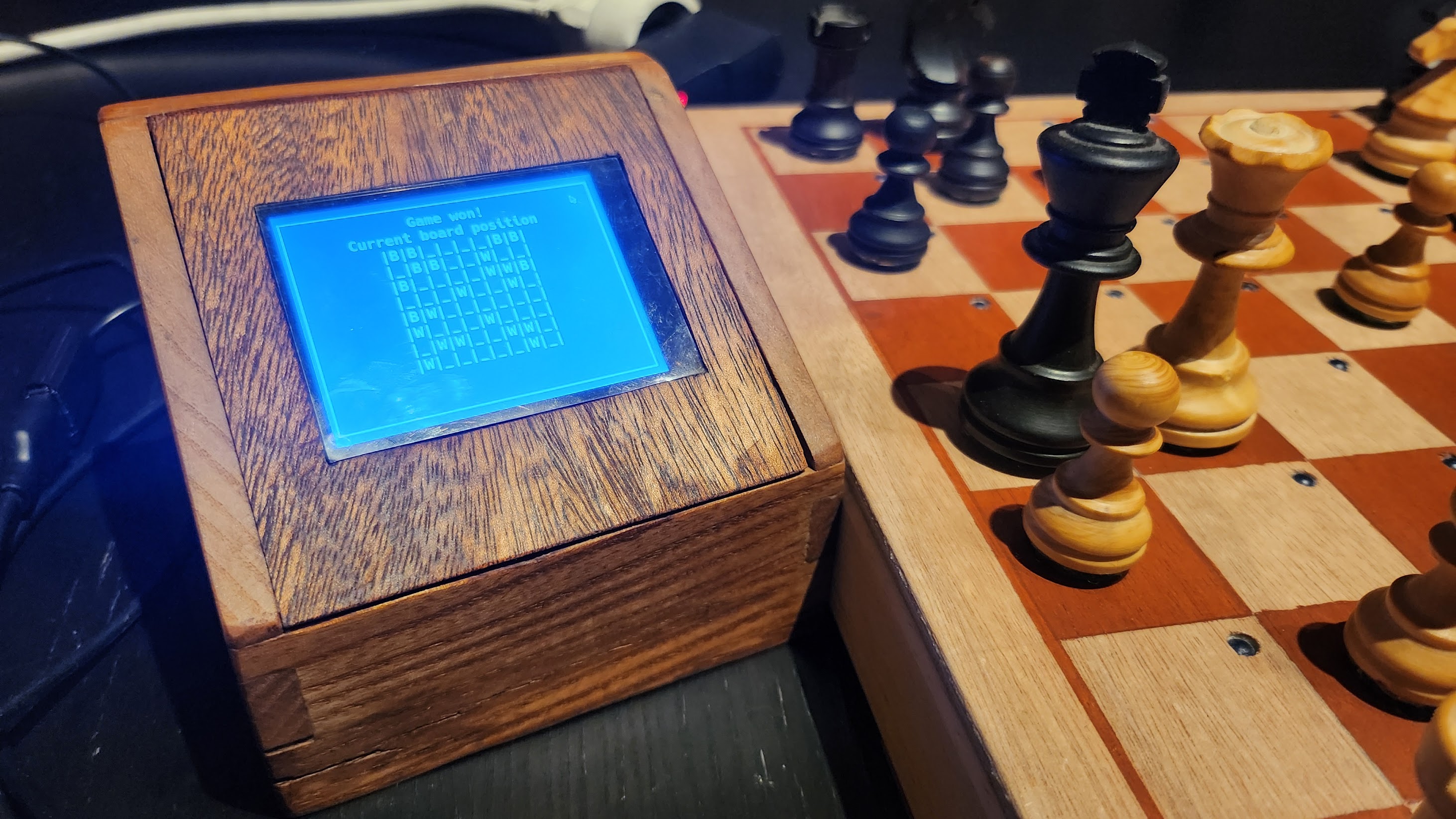
https://github.com/user-attachments/assets/bde2e431-92bb-4959-bb7b-e80072c71205
Demo game against a lichess bot. The phone showcases the game for demo purposes, but isn't actually required to play
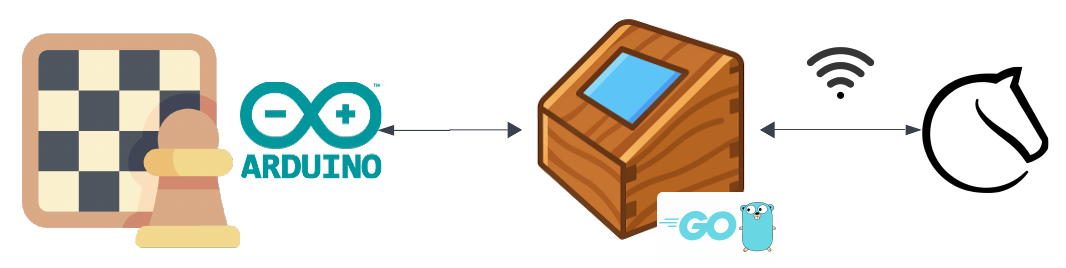
The general principle is to hide magnetic hall effect sensors under the board to detect piece presence. White & black pieces have a hidden magnet in them, in different orientations, respectively
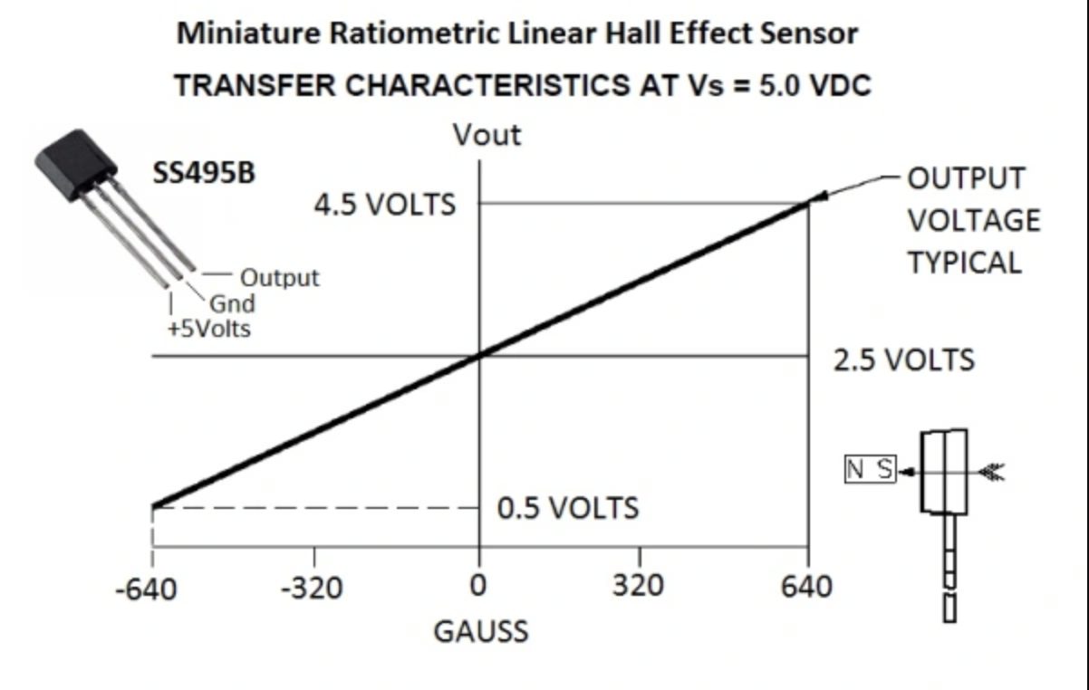
Using linear sensors we are then able to detect between 3 distinct states:
In addition to the sensors, a 8x8 LED matrix is used to display the opponent's moves on the board. An arduino microcontroller interfaces with an embedded go program to control the LEDs, read the sensors, and communicate with the lichess API.
Each square is equipped with a blue LED that can be lit to signal the opponent's move. It's bright enough that we don't miss a move, and discreet enough that it doesn't distract from the game.
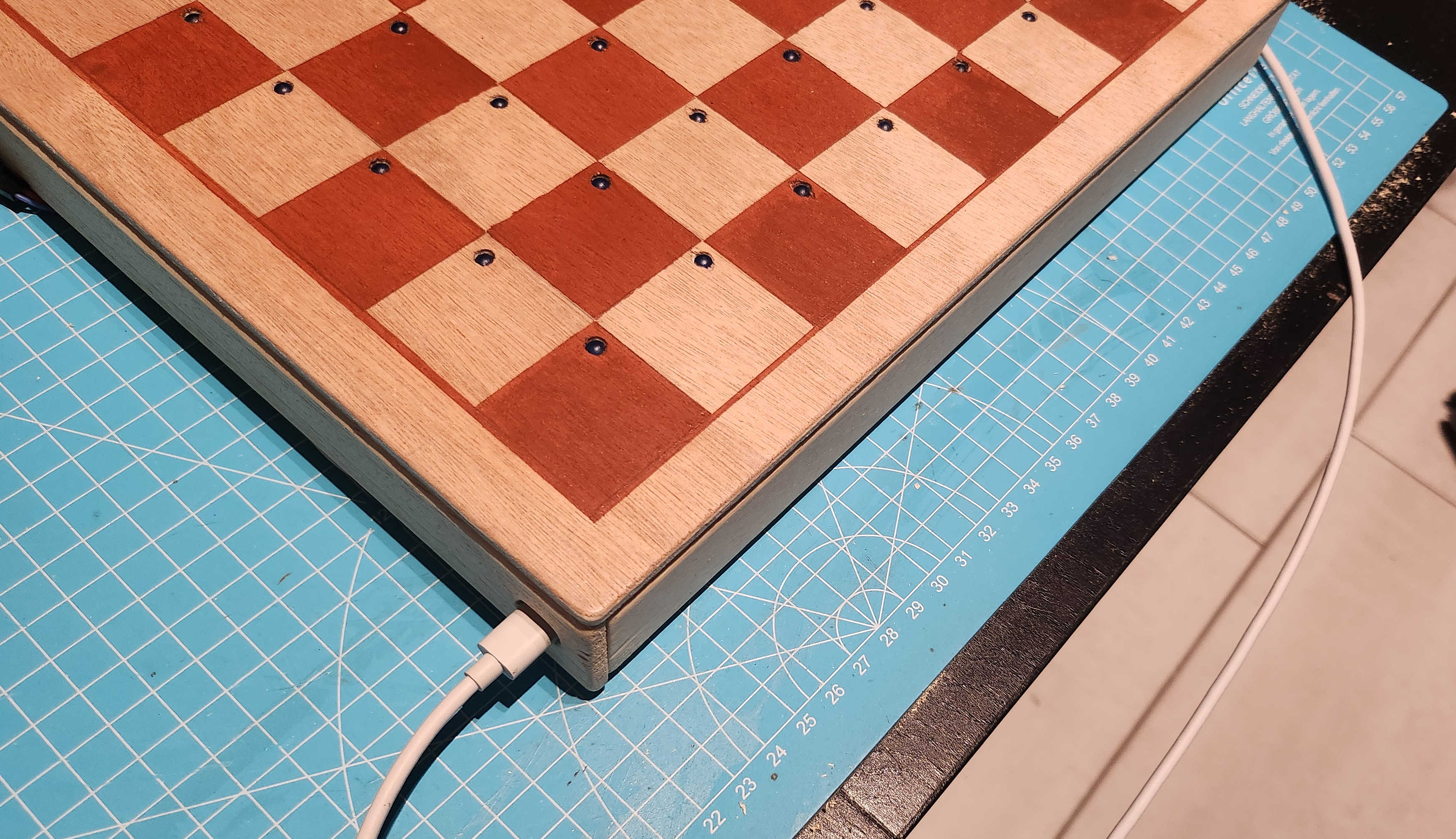
For the board to work, is is necessary to:
Since the arduino has a limited number of pins, two 74HC595 shift registers are used to control the LEDs with multiplexing, and an additional 74HC4051 multiplexer is used to control the sensor rows. Each of the sensor outputs are connected to one of the analog inputs of the microcontroller (arduino conveniently has 8 of them).
According to their spreadsheet, the power-on time of the the hall sensors is somewhere from 175μs to 300μs. This is slow enough that we can't use multiplexing to power the sensors. Instead I went for a 8x8 matrix where all of the sensors are always powered. Their input readings are then selected using some BJT transistors whose switch time is in the order of 30ns (so about 8 500 times faster than the sensors power-on time)
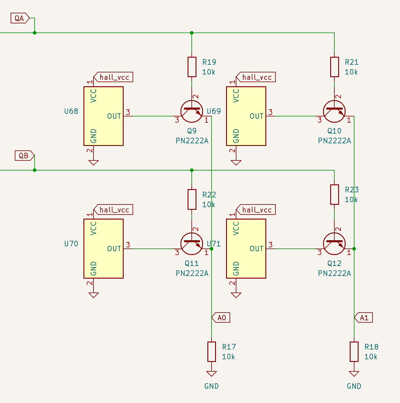 Details of the sensor matrix, only 4 sensors are shown. Sending QA=1, QB=0 and reading A1 input would provide a reading of the bottom-right sensor of this diagram
The three 74HC595 shift registers are chained, and connected to the arduino as follows(only 4 sensors are shown for simplicity):
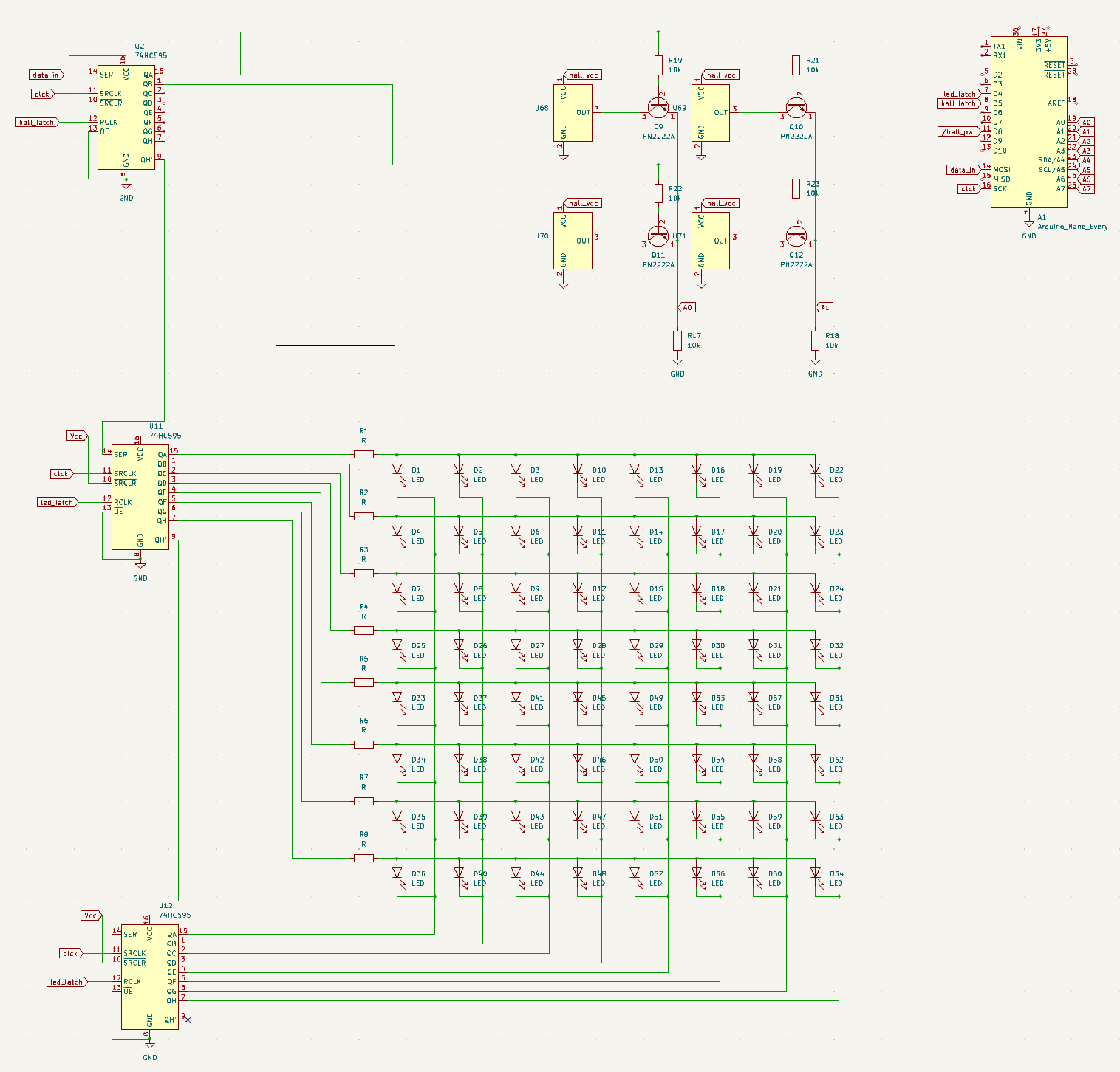 complete overview of the electronics. Full kiCad files can be found in the kiCad directory
With this setup, the microcontroller can use multiplexing to control the LEDs and read the sensors in near real time, while using very few pins from the microcontroller.
For the build I soldered 64 leds, hall effect sensors, and transistors directly to a wooden board I build and painted. The shift-register ICs are wired to the microcontroller thanks to a custom PCB whose files can be found here
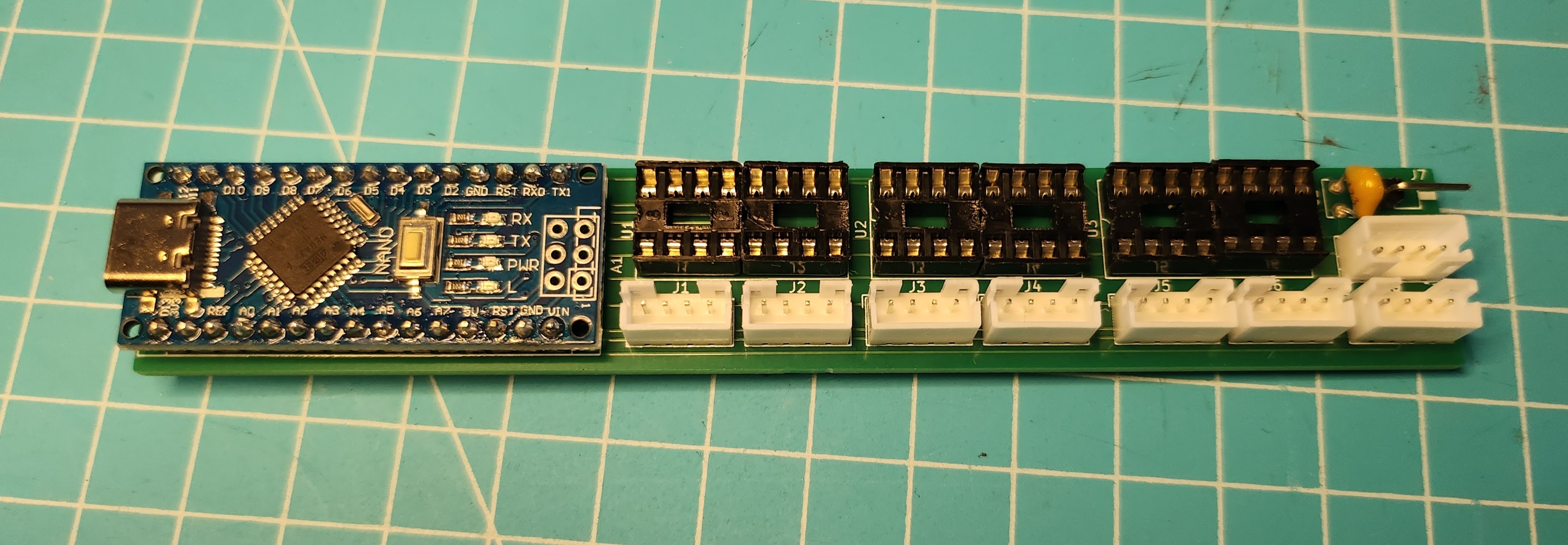 soldered pcb with arduino nano, IC sockets and some connectors
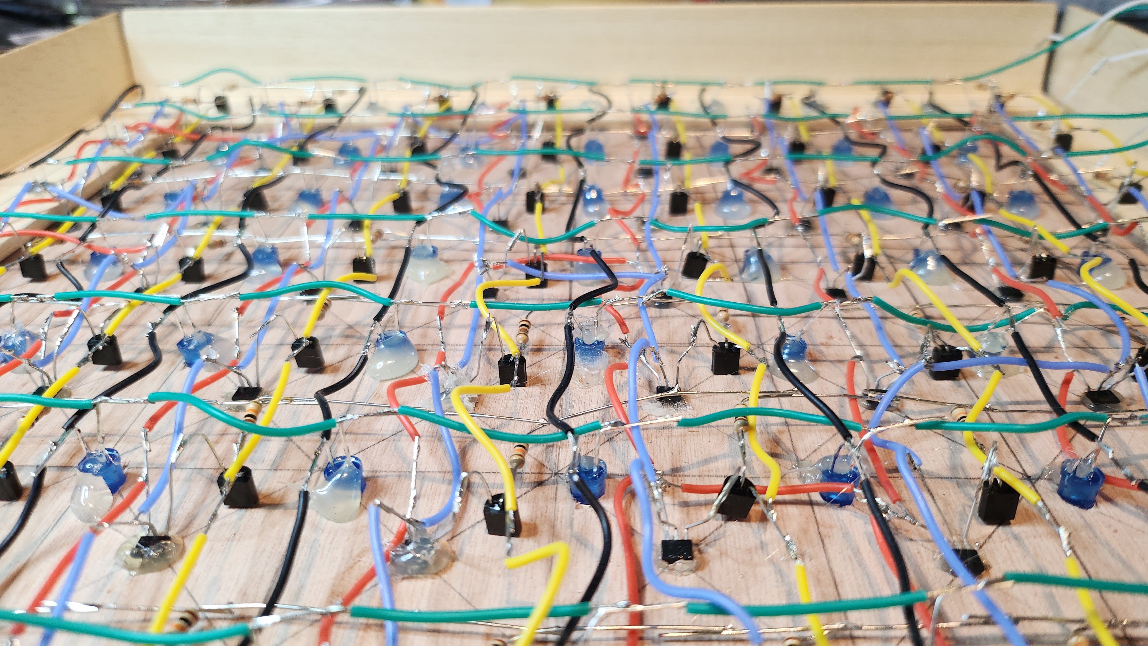 internal view of the board
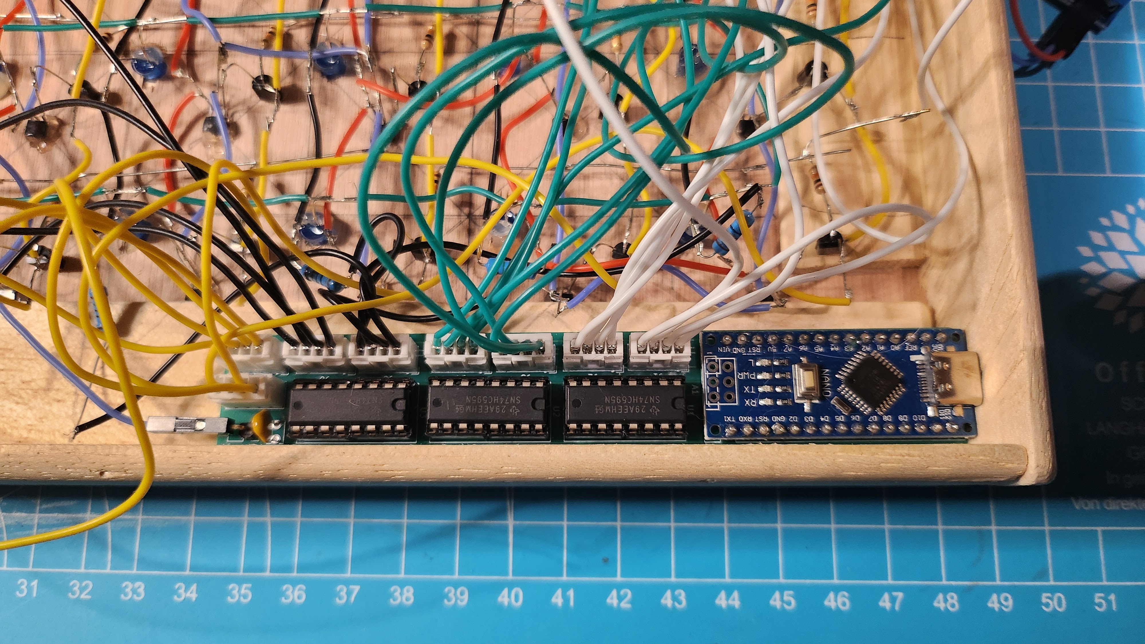 closeup of the pcb after installation
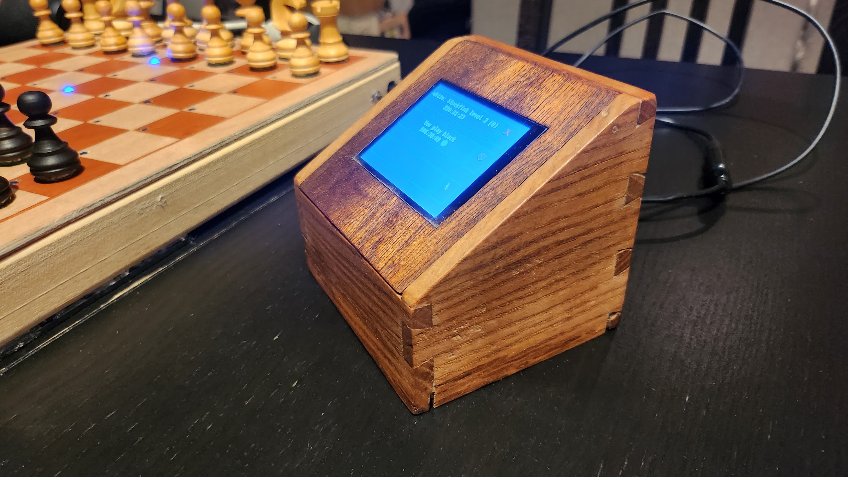
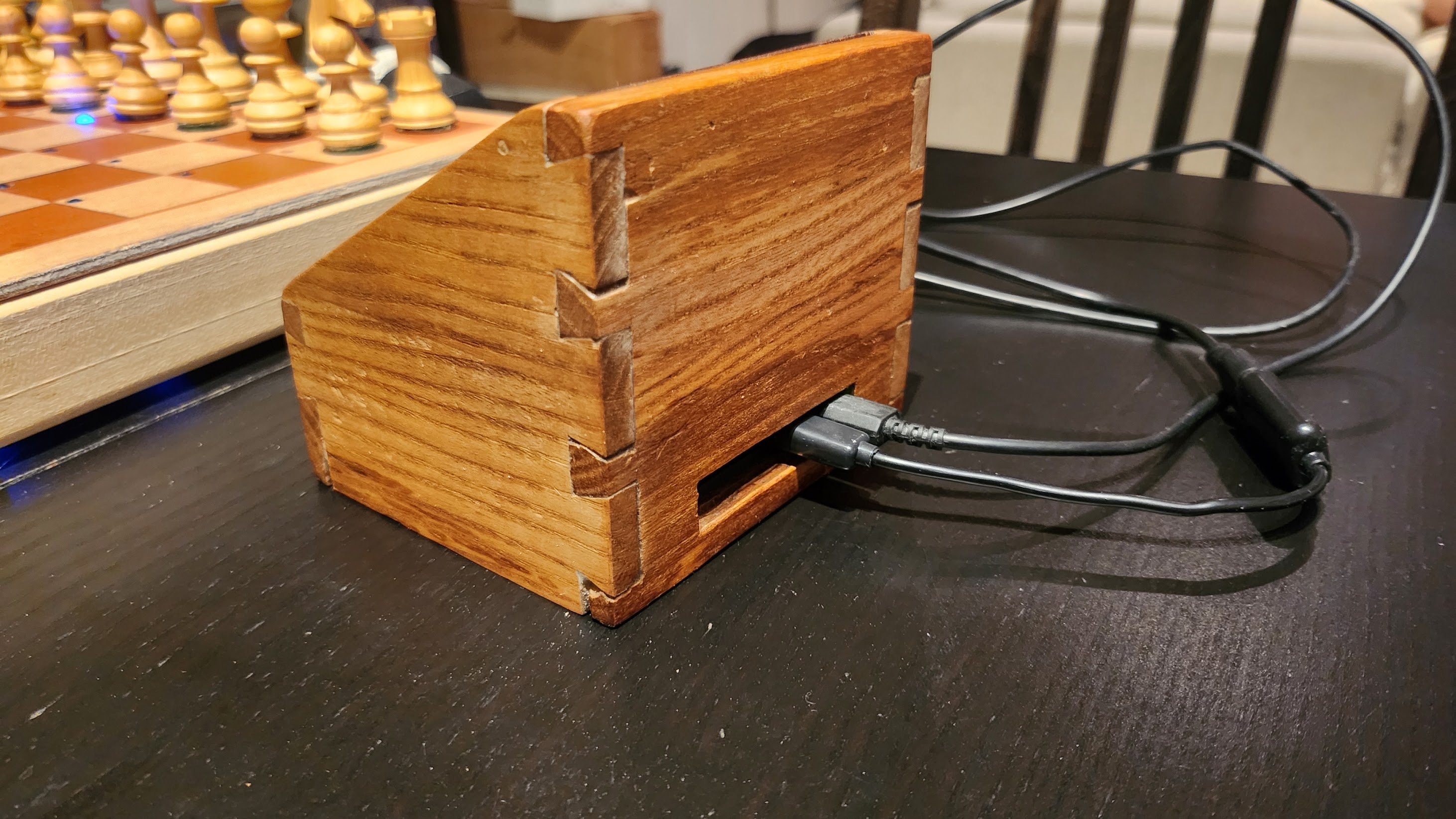
Arduino nano is used. It's cheap, small, and conveniently has 8 analog inputs, which is perfect for this use case.
The arduino loop does the following:
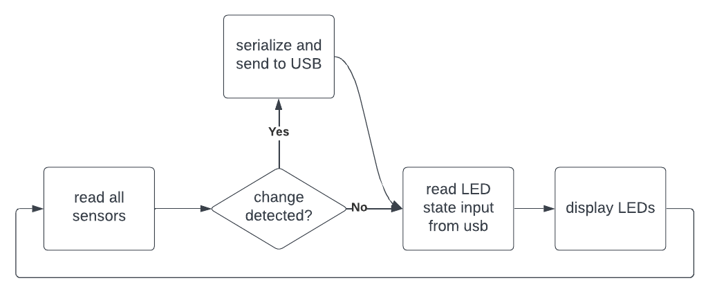
Read all the sensors
Using multiplexing, read all states from the 64 hall sensors and build a board state from it. If a state change is detected, then we serialize the board state and send it to the computer.
Read the LED input state
Read from usb and set the desired LED state
Display the LEDs
For each lit LED from the input state, light the corresponding LED on the board, wait 2ms, and turn it off.
Since we are multiplexing the display, the entire loop needs to be fast. Fast enough that you don't see any flickering while we are reading 64 sensors and communicating via USB between each LED blink.
A chess board has a very convenient size of 8x8, which allows to represent a row with exactly two bytes:
This protocol allows the board to send partial states between led blinks, which removes any flickering from the display. The program can wait for a (255, 255, 255) sequence to know that the board state is fully transmitted, and in case of data corruption, it can ignore a broken state, and start over everytime a (255, 255, 255) sequence is detected.
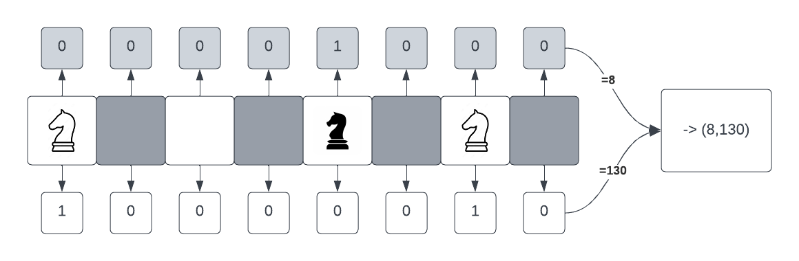 Example of how a row with 2 white pieces and 1 black piece would be encoded
Lastly, the main program is written in go, and communicates with the arduino. It will read both the board state and the game moves from lichess to reconcilate the position, and determine when a move should be played (i.e. sent to the server), or when some LEDs should be lit. The user interface is provided by a touchscreen, and everything runs on a raspberry zero.
The code can be found in the app directory
I've been playing with this board for quite a while now, and it has been a tremendous experience so far. It's definitely not suited for fast time controls, but lichess only provide their real-time API for rapid & classical time-controls anyway (has to do with anti-cheating measures I believe).
Playing lichess games while looking at a physical board is a delight, and has become my main way of playing chess at home.
| Qty | Value | Footprint | References |
|---|---|---|---|
| 8 | Conn_01x04_Socket | Connector_JST:JST_PH_B4B-PH-K_1x04_P2.00mm_Vertical | J1, J2, J3, J4, J5, J6, J8, J9 |
| 3 | 74HC595 | Package_DIP:DIP-16_W7.62mm_Socket | U1, U2, U3 |
| 1 | Arduino_Nano_Every | Module:Arduino_Nano | A1 |
| 1 | C | Capacitor_THT:C_Disc_D3.8mm_W2.6mm_P2.50mm | C2 |
| 1 | Conn_01x01_Socket | Connector_PinHeader_2.54mm:PinHeader_1x01_P2.54mm_Horizontal | J7 |
It measures 127 × 20.7 mm and has 2 copper layers, 1.6 mm thick.
14 parts, built around the 74HC595. The full list of its parts is on this page, with links to each part's symbol and footprint where PCBKit's library has them.
From the aherve/eChess repository on GitHub, at the commit this page was made from: the board is eBoard_pcb/eBoard_pcb.kicad_pcb and its schematic eBoard_pcb/eBoard_pcb.kicad_sch. PCBKit opens the board in the browser, with nothing to install.
Its repository publishes it under the AGPL-3.0 licence: you may reuse it on that licence's terms (keep the author's notice, and for a copyleft licence share your changes alike).
tardate/LittleArduinoProjects
a collection of "Little Electronic & Arduino Projects", most involving electronics or an Arduino in one way or another!

ChrisChrisLoLo/beyblock20
The magnetic, modular, 20-key macropad that can join together to form an ortholinear board

slu4coder/Minimal-64x4-Home-Computer
My DIY TTL home computer with VGA and PS/2 and 4x the processing power of a Commodore C64 or Apple II.

electroniceel/protoboard
Advanced protoboard layout with 1.27mm pitch for smd parts

TobleMiner/DC-UPS
A small DC UPS, designed to keep small appliances like consumer network equipment running during power outages


