External Water-Cooling Loop Controller
The intent of this project is to monitor and control an external chiller system for a PC water-cooling loop with a liquid-liquid heat exchanger to separate the internal and external loops.
There is a PCIe x1 card inside the PC, tapping into SMBus and +3V3AUX, to monitor the flow, inlet, and outlet temperatures for the internal and external loops, and intercept the front panel power switch to prevent boot or to initiate a shutdown if the loops are not working correctly. The Teensy 3.2 will communicate to the PC, pretending to be a common SMBus device such as those from Winbond or Nuvoton. It also talks with an external board in the chiller over RS232. Onboard WS2811B and an OLED screen show immediate diagnostics. An onboard BME280 lets the Teensy monitor internal case ambient temperature and humidity, to ensure that the chiller does not drop below the local dewpoint to prevent condensation.
The external board listens to RS232 and adjusts the chiller's power state and setpoint. It also reports the local BME280 results and has an onboard OLED screen for system status.
Internal PCIe Card
| Pin | Type | Signal | Direction | Purpose |
|---|
| 1 | POWER | GND | | Digital ground plane |
| 2 | DIGITAL | D0 | INPUT | Internal loop flow sensor |
| 3 | DIGITAL | D1 | INPUT | External loop flow sensor |
| 7 | DIGITAL | D5 | OUTPUT | Level shifter output enable, active low |
| 8 | DIGITAL | D6 | INPUT | PCIe #PERST status |
| 9 | DIGITAL | D7 | OUTPUT | WS2811B data |
| 11 | RS232 | RX | INPUT | RS232 receive |
| 12 | RS232 | TX | OUTPUT | RS232 transmit |
| 21 | ANALOG | A0 | INPUT | External loop outflow temperature, 10k NTC |
| 22 | ANALOG | A1 | INPUT | External loop inflow temperature, 10k NTC |
| 23 | ANALOG | A2 | INPUT | Internal loop inflow temperature, 10k NTC |
| 24 | ANALOG | A3 | INPUT | Internal loop outflow temperature, 10k NTC |
| 25 | I2C | SDA0 | BIDI | SMBus I2C data |
| 26 | I2C | SCL0 | BIDI | SMBus I2C clock |
| 29 | DIGITAL | D22 | OUTPUT | Front panel power switch output |
| 30 | DIGITAL | D23 | INPUT | Front panel power switch input |
| 31 | POWER | 3V3 | | 3.3V AUX input |
| 32 | POWER | AGND | | Analog ground plane |
| 42 | POWER | 3V3 | | 3.3V AUX input |
| 46 | I2C | SDA1 | BIDI | Local I2C data |
| 47 | I2C | SCL1 | BIDI | Local I2C clock |
| 53 | POWER | GND | | Digital ground plane |
WS2811B
- External loop temperature status
- External loop flow status
- Internal loop temperature status
- Internal loop flow status
RS232 DE-9
- Chassis earth
- N/C
- PC RX
- PC TX
- N/C
- 0VDC
- N/C
- N/C
- N/C
- +5V
Images
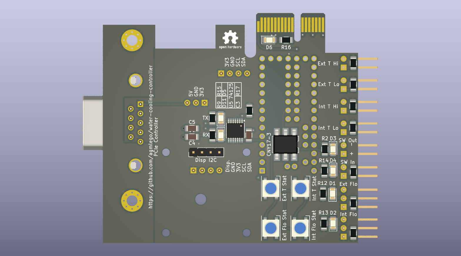
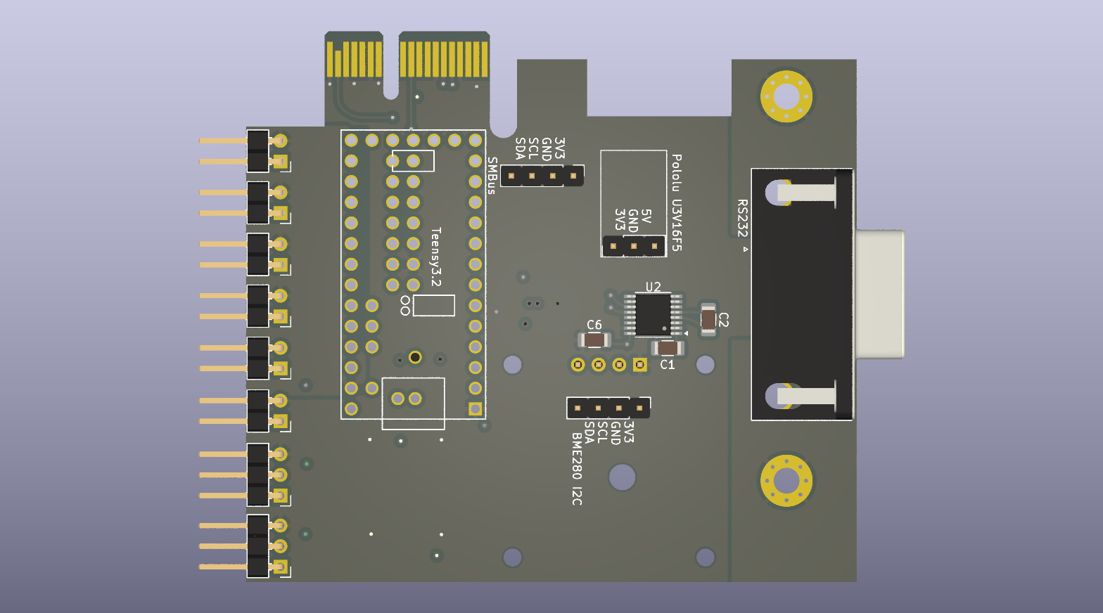 Interactive BOM
Chiller Controller
| Pin | Type | Signal | Direction | Purpose |
|---|
| 1 | POWER | GND | | Digital ground |
| 2 | RS232 | RX | INPUT | RS232 receive |
| 3 | RS232 | TX | OUTPUT | RS232 transmit |
| 4 | 1-WIRE | D2 | BIDI | DS18B20 bus |
| 10 | DIGITAL | D8 | OUTPUT | Expansion valve relay |
| 11 | DIGITAL | D9 | OUTPUT | Compressor relay |
| 12 | DIGITAL | D10 | OUTPUT | Fan PWM |
| 13 | DIGITAL | D11 | INPUT | Bottom fan RPM sensor |
| 14 | DIGITAL | D12 | INPUT | Top fan RPM sensor |
| 20 | DIGITAL | D13 | OUTPUT | Status lights/buzzer relay |
| 21 | DIGITAL | D14 | OUTPUT | Pump relay |
| 22 | DIGITAL | D15 | INPUT | Flow switch, active low |
| 23 | I2C | SCL0 | BIDI | Local I2C clock |
| 24 | I2C | SDA0 | BIDI | Local I2C data |
| 25 | DIGITAL | D18 | INPUT | Encoder switch |
| 26 | DIGITAL | D19 | INPUT | Encoder quadrature B |
| 27 | DIGITAL | D20 | INPUT | Encoder quadrature A |
| 28 | ANALOG | A7 | INPUT | Filter check diff. pressure sensor |
| 29 | ANALOG | A8 | INPUT | Reservoir eTape Rref 2000Ω |
| 30 | ANALOG | A9 | INPUT | Reservoir eTape Rsense 400-2000Ω |
| 31 | POWER | 3V3 | | 3.3V output |
| 32 | POWER | AGND | | Analog ground |
| 33 | POWER | 5V | | 5V input from CAN |
JST-XH Connectors
RS232
| Pin | Type | Signal | Direction | Purpose |
|---|
| 1 | POWER | 5V | | 5V from PCIe card |
| 2 | POWER | GND | | Digital ground |
| 3 | RS232 | RX | INPUT | RS232 receive |
| 4 | RS232 | TX | OUTPUT | RS232 transmit |
Flow
| Pin | Type | Signal | Direction | Purpose |
|---|
| 1 | DIGITAL | D15 | INPUT | Flow switch |
| 2 | POWER | GND | | Digital ground |
DS18B20 One-Wire
| Pin | Type | Signal | Direction | Purpose |
|---|
| 1 | 1-WIRE | D2 | BIDI | DS18B20 bus |
| 2 | POWER | GND | | Digital ground |
| 3 | POWER | 3V3 | | 3.3V output |
Filter Diff. Pressure
| Pin | Type | Signal | Direction | Purpose |
|---|
| 1 | POWER | 3V3 | | 3.3V output |
| 2 | POWER | AGND | | Analog ground |
| 3 | ANALOG | A7 | INPUT | Filter check diff. pressure sensor |
Reservoir Level eTape
| Pin | Type | Signal | Direction | Purpose |
|---|
| 1 | ANALOG | A9 | INPUT | Rsense 400-2000Ω |
| 2 | ANALOG | A8 | INPUT | Rref 2000Ω |
| 3 | POWER | AGND | | Analog ground |
| 4 | POWER | AGND | | Analog ground |
Fans
| Pin | Type | Signal | Direction | Purpose |
|---|
| 1 | DIGITAL | D12 | INPUT | Top fan RPM sensor |
| 2 | DIGITAL | D11 | INPUT | Bottom fan RPM sensor |
| 3 | DIGITAL | D10 | OUTPUT | Fan PWM |
Dual-Relay Module
| Pin | Type | Signal | Direction | Purpose |
|---|
| 1 | POWER | GND | | Digital ground |
| 2 | DIGITAL | D13 | OUTPUT | Status lights/buzzer relay |
| 3 | DIGITAL | D14 | OUTPUT | Pump relay |
| 4 | POWER | 5V | | 5V input from CAN |
SSRs
| Pin | Type | Signal | Direction | Purpose |
|---|
| 1 | POWER | GND | | Digital ground |
| 2 | DIGITAL | D9 | OUTPUT | Compressor relay |
| 3 | POWER | GND | | Digital ground |
| 4 | DIGITAL | D8 | OUTPUT | Expansion valve relay |
NF-A14 Control
- PWM: 40μs period, 5Vpp
- 8.76% minimum kickon => 468RPM (64ms/15.6Hz on tach.)
- 100% => 3180RPM (9.4ms/106.4Hz on tach.)
Images
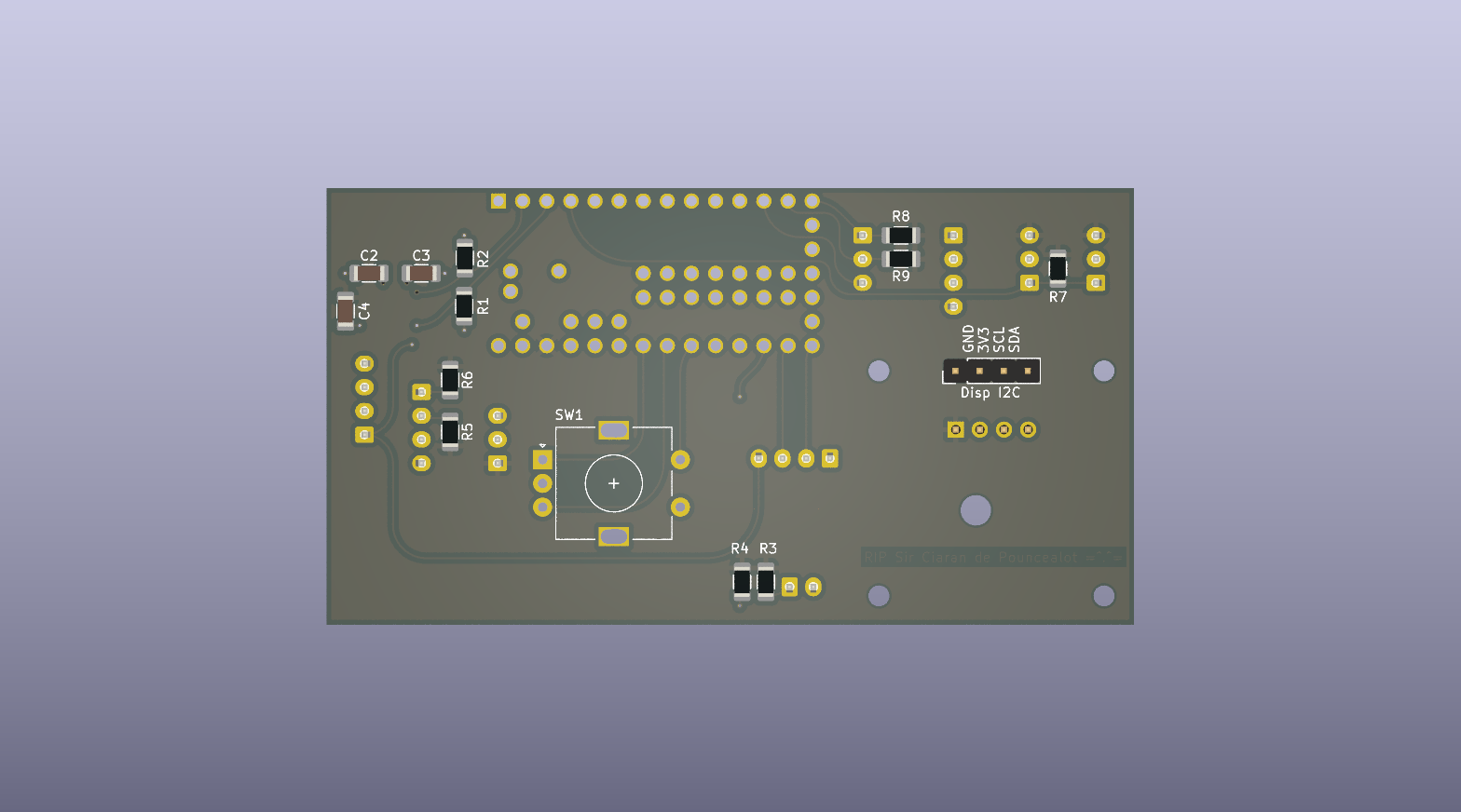
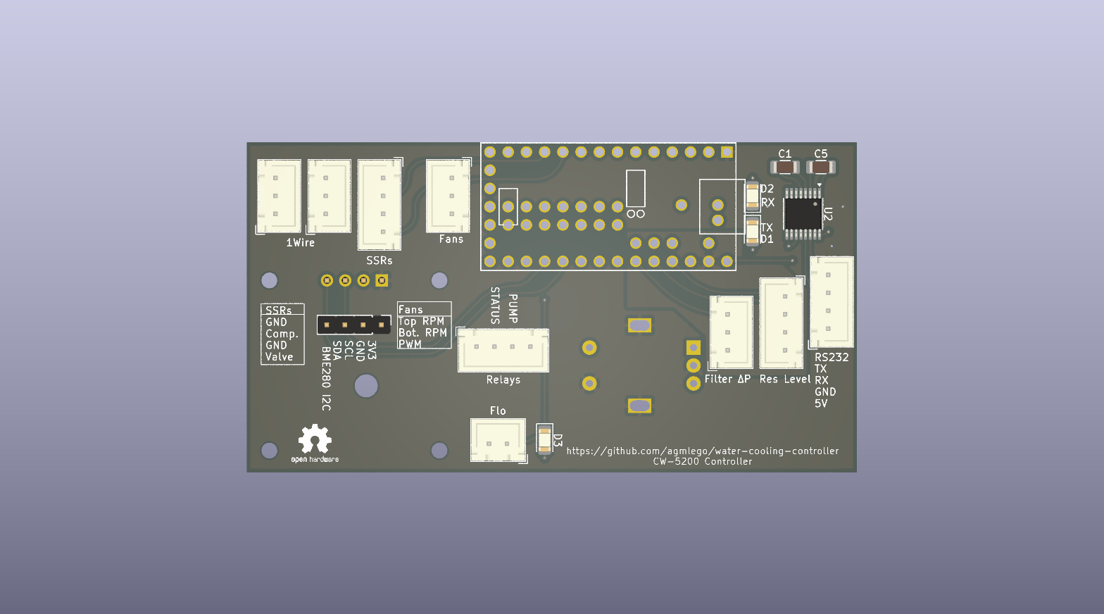 Interactive BOM


