2 layers27.9 × 16.5 mm

 agilfor/wakey-wakey
wakey-wakey is a simple alarm clock built on a Seeed Studio XIAO ESP32C3. It runs on C++.
Wakey wakey is an open-source printed circuit board by agilfor, from the agilfor/wakey-wakey repository on GitHub. It is a 2-layer board of 78 × 49 mm with 18 parts on 20 nets, routed with 108 tracks and 0 vias.
Its parts include 4 diodes, 4 switches, 2 resistors, 2 connectors and 1 IC. It belongs with the ESP32 and RISC-V boards of this library.
wakey-wakey is a simple alarm clock built on a Seeed Studio XIAO ESP32C3. It runs on C++.
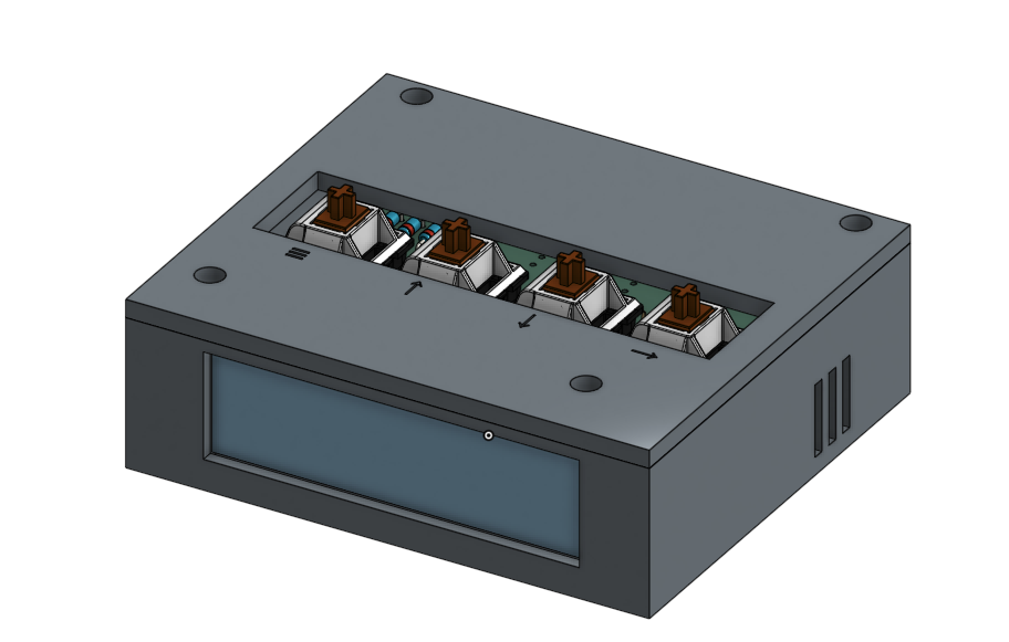
The goal of this model was to make it as symmetrical as possible and as minimalistic as possible. The idea is for it to look simple and be functional as an alarm clock should be.
The current design was made in Onshape. It has screwholes for the PCB, a slot for the TFT display, holes for the buzzer sound, a gap for a USB-C cable, and a top cover with the functions of the buttons engraved.
My PCB was made in KiCad. I went a bit more crazy with this than with the CAD, so it took a while. It has 4 keys Charlieplexed to 3 pins, a buzzer, and a TFT display with all pins connected. Additionally, it has been designed with battery functionality in mind. It has a pin header to connect a battery cell to the ESP32C3 VBAT and GND pins (requires some soldering), and uses a nifty voltage divider (with two 220kΩ resistors) connected to an analog pin to allow for battery level measurements. Though these parts fall outside of the standard kit, I have them at home so decided to add them because it's cool and because why not ¯\_(ツ)_/¯
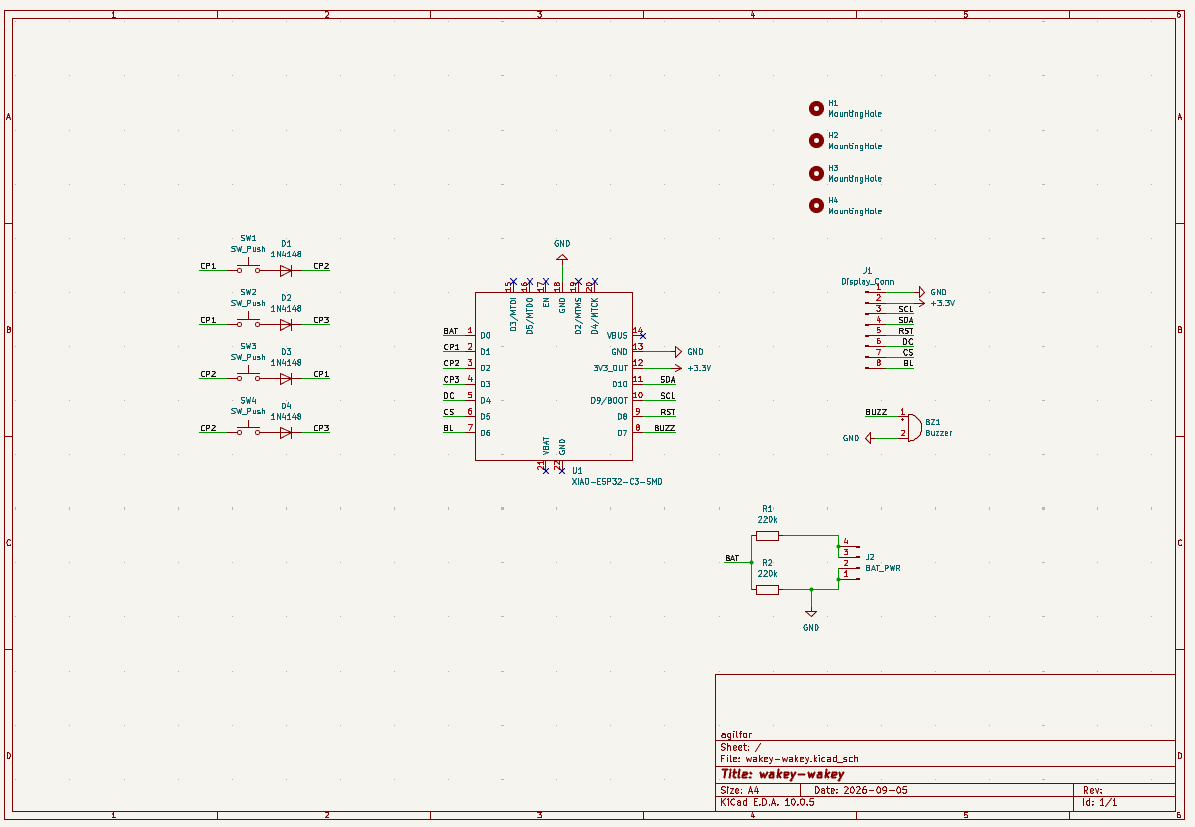
This is my current schematic. It uses charlieplexing to wire the keys (which is how I made space for the battery pin). The downside is it means I need to write more firmware to make it work. Other than that it's not very complicated. There are technically some wires missing (VBAT, GND, and the whole BAT_PWR block) as those require soldering. More info about the battery trick.
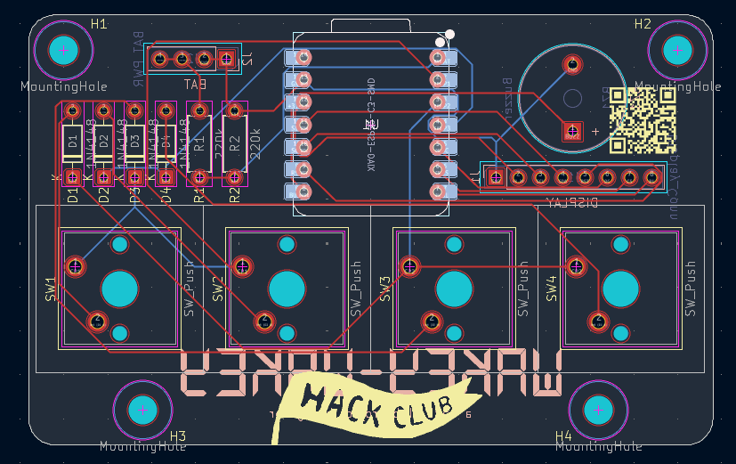
This is my PCB. The routing wasn't particularly difficult, but I had fun with it. I mostly ended up making life difficult for myself by trying to make it as small as possible. Also, I spent way too long on the silkscreen designs but no regrets :)
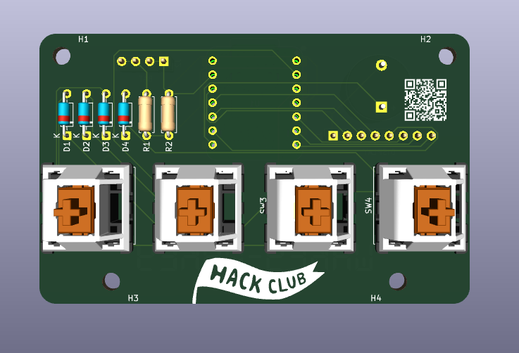
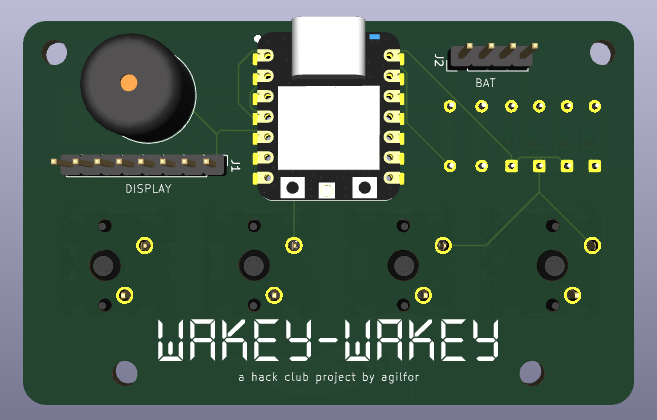
Due to the mount style of the XIAO ESP32C3, it is not possible to easily connect the battery pads under the microcontroller to the PCB (technically this is possible using a SMD mount, but it is a pain and much simpler to do some soldering with a DIP mount). The 4 pin male header is the connection of the battery to the microcontroller. It has 4 pins as it requires two pins for VCC and two for GND (connection to the battery cell and connection to the microcontroller). For a more detailed explanation please consult the battery.md doc.
The wakey-wakey uses C++ firmware for everything. Currently it supports deep sleep and waking on button press. It should also be able to draw to the TFT display.
Support still needs to be added for all the Wi-Fi functionalities, as well as the alarm, 24H time view toggle, and more. This will be done post-assembly, as some testing needs to be done with the charlieplexed keys before making the script more complicated than it already is.
There will probably be more changes as well to the firmware after all this, but that remains TBD.
Extra:
| Qty | Value | Footprint | References |
|---|---|---|---|
| 4 | 1N4148 | Diode_THT:D_DO-35_SOD27_P7.62mm_Horizontal | D1, D2, D3, D4 |
| 4 | MountingHole | MountingHole:MountingHole_3.2mm_M3 | H1, H2, H3, H4 |
| 4 | SW_Push | Button_Switch_Keyboard:SW_Cherry_MX_1.00u_PCB | SW1, SW2, SW3, SW4 |
| 2 | 220k | Resistor_THT:R_Axial_DIN0207_L6.3mm_D2.5mm_P7.62mm_Horizontal | R1, R2 |
| 1 | BAT_PWR | Connector_PinHeader_2.54mm:PinHeader_1x04_P2.54mm_Vertical | J2 |
| 1 | Buzzer | Buzzer_Beeper:Buzzer_12x9.5RM7.6 | BZ1 |
| 1 | Display_Conn | Connector_PinHeader_2.54mm:PinHeader_1x08_P2.54mm_Vertical | J1 |
| 1 | XIAO-ESP32-C3-SMD | blare:XIAO-ESP32-C3-DIP | U1 |

VoronDesign/Voron-Hardware
Cool Hardware designed by the Voron Design group


hackclub/OnBoard
💡 Join 1,000 teenagers and make your first PCB with a $100 grant!

VoronDesign/Voron-Tap
Tap is a nozzle-based z-probe for the V2 and Trident printer designs. The entire toolhead moves to trigger an optical switch. Tap offers many advantages:

Luos-io/luos_engine
Open-source and real-time orchestrator for cyber-physical-systems, to easily design, test and deploy embedded applications and digital twins.


Twotoz/C5VRX
Ultra-minimal, zero-CPU 5.8 GHz analog FPV video receiver using ESP32-C5 Wi-Fi 6 PHY MODEM_DIAG, BitScrambler WBFM demodulation & resistor DAC CVBS
It measures 78 × 49 mm and has 2 copper layers, 1.6 mm thick.
18 parts. The full list of its parts is on this page, with links to each part's symbol and footprint where PCBKit's library has them.
From the agilfor/wakey-wakey repository on GitHub, at the commit this page was made from: the board is PCB/wakey-wakey.kicad_pcb and its schematic PCB/wakey-wakey.kicad_sch. PCBKit opens the board in the browser, with nothing to install.
Its repository states no licence, so its author keeps all rights: ask agilfor before reusing the design.