
4 layers234 × 84 mm
Main panel
google/mozc-devices
Circuit diagrams and firmware source code for Gboard DIY keyboards
234 parts3kApache-2.0

 agilfor/maxpad
Maxpad is a 12 key macropad with two rotary encoders, an OLED display, and 20 LEDs. It runs on QMK firmware.
Hackpad is an open-source printed circuit board by agilfor, from the agilfor/maxpad repository on GitHub. It is a 2-layer board of 100 × 90 mm with 48 parts on 46 nets, routed with 539 tracks and 43 vias.
It is built around the SK6812MINI-E. Its parts include 20 inductors, 14 switches, 12 diodes and 2 ICs. It belongs with the keyboards and input boards of this library.
Maxpad is a 12 key macropad with two rotary encoders, an OLED display, and 20 LEDs. It runs on QMK firmware.
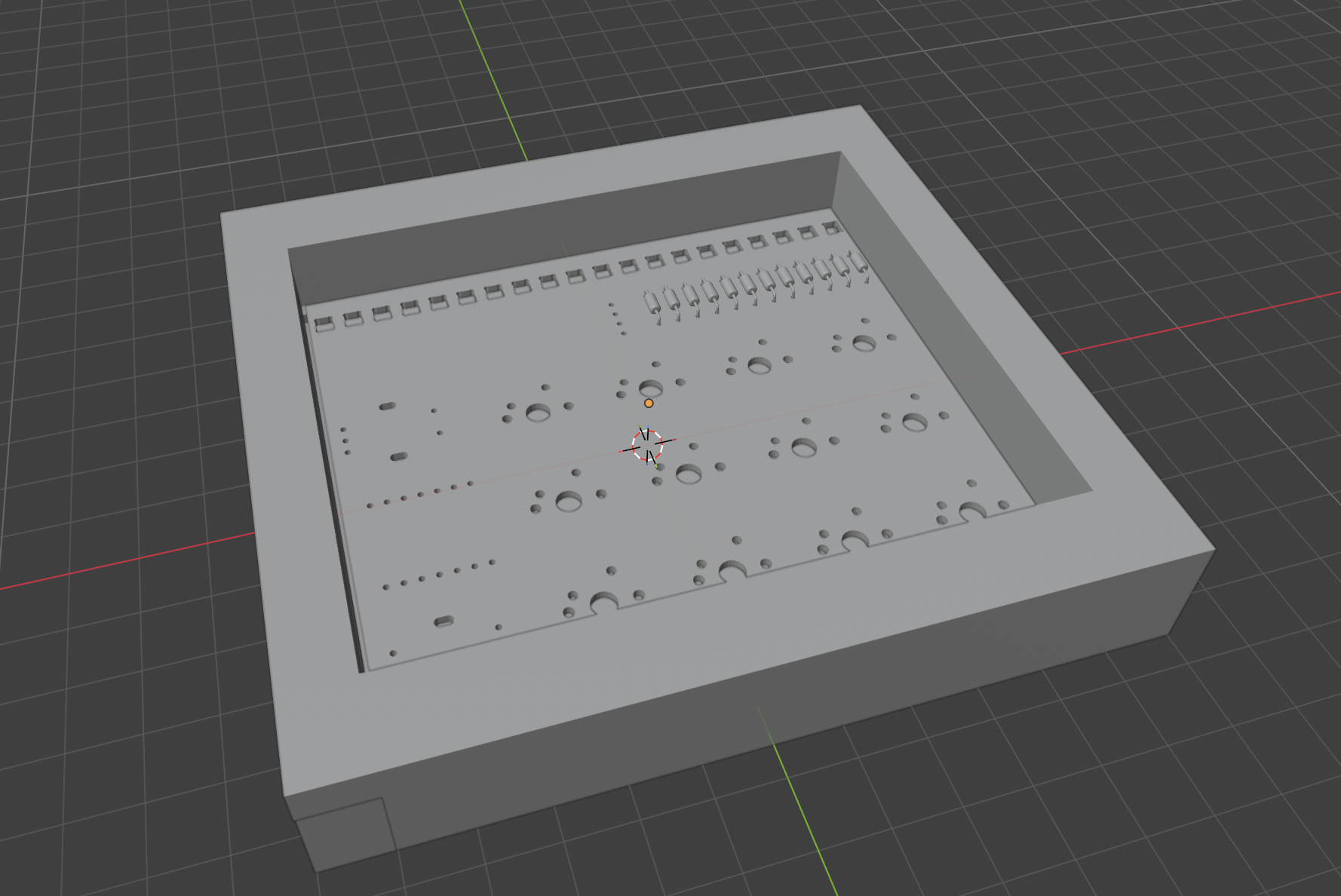
The idea is for the PCB to slide into the main body in a printed groove. The body can be locked with a second 3D-printed piece, and two M3x5x4mm heat insets and two M3x16mm screws.
The current design is simply to hold the PCB, but doesn't yet incorporate a keyplate or any real coverings. This may be added in a v2 of the CAD design, but for now the priority is getting the current setup to be functional. The design was made in Blender.
My PCB was made in KiCad. It doesn't incorporate a lot of fancy silkscreen images (although I would've liked to) as I needed the space to fit components within the size limit.
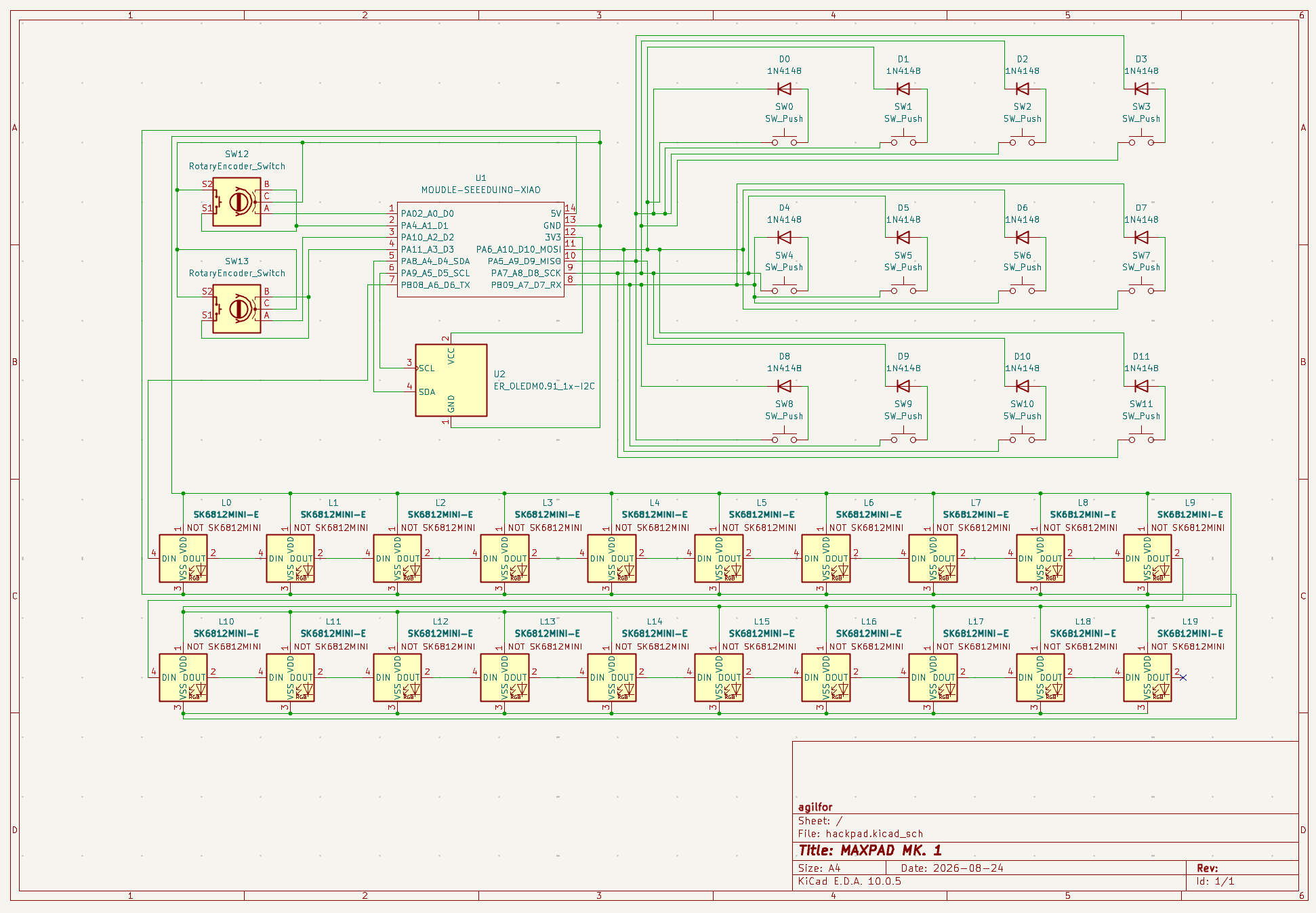
This is my current schematic. It uses charlieplexing to wire the keys (which is how I fit in so many with only 4 pins). The downside is it means I need to write more firmware to make it work. In hindsight, I should really have used net labels when making this, but it was my first time and I didn't know ¯\_(ツ)_/¯
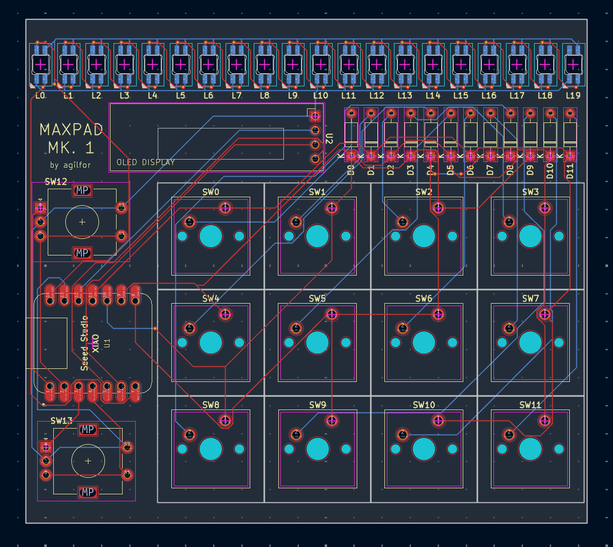
This is my PCB. The routing was difficult mostly cuz there are so many components and I had a size limit. It was fun to make though :)
The maxpad uses QMK firmware for everything. Currently it should support 12 customizeable keys and 2 customizeable rotary encoders.
Support still needs to be added for the OLED and LEDs. This is a WIP and will be done post assembly.
There will probably be more changes as well to the firmware after all this, but that remains TBD.
| Qty | Value | Footprint | References |
|---|---|---|---|
| 20 | SK6812MINI-E | hackpad:SK6812MINI-E_fixed | L0, L1, L2, L3, L4, L5, L10, L11, L12, L13, L14, L15, L16, L17, L18, L19 +4 |
| 12 | 1N4148 | Diode_THT:D_DO-35_SOD27_P7.62mm_Horizontal | D0, D1, D2, D3, D4, D5, D6, D7, D8, D9, D10, D11 |
| 12 | SW_Push | Button_Switch_Keyboard:SW_Cherry_MX_1.00u_PCB | SW0, SW1, SW2, SW3, SW4, SW5, SW6, SW7, SW8, SW9, SW10, SW11 |
| 2 | RotaryEncoder_Switch | hackpad:RotaryEncoder_Alps_EC11E-Switch_Vertical_H20mm | SW12, SW13 |
| 1 | ER_OLEDM0.91_1x-I2C | Display:ER_OLEDM0.91_1x-I2C | U2 |
| 1 | MOUDLE-SEEEDUINO-XIAO | hackpad:XIAO-Generic-Hybrid-14P-2.54-21X17.8MM | U1 |
It measures 100 × 90 mm and has 2 copper layers, 1.6 mm thick.
48 parts, built around the SK6812MINI-E. The full list of its parts is on this page, with links to each part's symbol and footprint where PCBKit's library has them.
From the agilfor/maxpad repository on GitHub, at the commit this page was made from: the board is src/PCB/hackpad.kicad_pcb and its schematic src/PCB/hackpad.kicad_sch. PCBKit opens the board in the browser, with nothing to install.
Its repository states no licence, so its author keeps all rights: ask agilfor before reusing the design.
google/mozc-devices
Circuit diagrams and firmware source code for Gboard DIY keyboards

Bastardkb/Dilemma
The Dilemma is a vertical stagger low-profile keyboard with mods.

Pwnsat/FlatSat
Flatsat v1.0 is a hardware based platform for aerospace cybersecurity research

adamws/kicad-kbplacer
KiCad plugin for automatic keyboard's key placement and routing

imchipwood/dumbpad
Simple 4x4 numpad with rotary encoder. Powered by QMK via ATmega32u4 Pro Micro

makerforgetech/modular-biped
An open source framework for creating a bipedal modular companion robot.

