
2 layers82.8 × 63 mm
 agausmann/WindowMaster3
A physical controller for the Windows Volume Mixer (sndvol)
WindowMaster is an open-source printed circuit board by agausmann, from the agausmann/WindowMaster repository on GitHub. It is a 2-layer board of 100 × 50 mm with 81 parts on 68 nets, routed with 509 tracks and 26 vias.
It is built around the STM32F072C8T6. Its parts include 42 resistors, 18 capacitors, 9 switches, 8 diodes and 2 ICs. It belongs with the STM32 boards of this library.
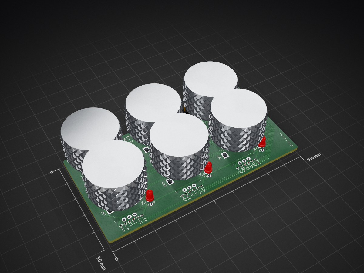
This circuit board is the main board for the WindowMaster physcial controller. It supports 6 control channels which can be individually assigned to different channels via the WindowMaster software.
The MCU powering this board is an STM32F072C8, which can read the encoder states and set indicators via GPIO, and communicate with the host computer over USB. You can flash the provided firmware to communicate with and control the WindowMaster host software, or write and flash your own if you have another usecase for the control surface. (In the future, I may provide other firmwares to turn it into a generic input device like a joystick or MIDI. Feel free to contact me if you'd like to commission a custom firmware - I'd love to hear about your idea!)
This board is developed with KiCad version 5.1.9. Components, especially those that can or must be surface-mounted, are picked from the JLCPCB SMT Parts Library, if there is a suitable part there. This makes it more convenient to fabricate and assemble, as they will do most of the work. Everything else is picked to be easy to hand-solder with an iron, which generally means through-hole or large tabs.
TODO
The PCB is laid out into six channels. Each channel has its own quadrature encoder (PEC11R), a pushbutton switch (built into the encoder), and an indicator LED. These peripherals are controlled by the onboard STM32F072C8 microcontroller, which is also given a USB port so it can communicate with a host system.
Here is the pinout of the STM32 chip to all of its connected peripherals, for quick reference while programming:
| Physical | Logical | Description | Direction | Logic |
|---|---|---|---|---|
| 25 | PB12 | Status LED | Output | Active Low |
| 32 | PA11 | USB D- | ||
| 33 | PA12 | USB D+ | ||
| 3 | PC14 | Channel 1 Encoder A | Input | Active Low |
| 2 | PC13 | Channel 1 Encoder B | Input | Active Low |
| 39 | PB3 | Channel 1 Pushbutton | Input | Active Low |
| 40 | PB4 | Channel 1 Indicator | Output | Active Low |
| 46 | PB9 | Channel 2 Encoder A | Input | Active Low |
| 45 | PB8 | Channel 2 Encoder B | Input | Active Low |
| 38 | PA15 | Channel 2 Pushbutton | Input | Active Low |
| 41 | PB5 | Channel 2 Indicator | Output | Active Low |
| 43 | PB7 | Channel 3 Encoder A | Input | Active Low |
| 42 | PB6 | Channel 3 Encoder B | Input | Active Low |
| 27 | PB14 | Channel 3 Pushbutton | Input | Active Low |
| 28 | PB15 | Channel 3 Indicator | Output | Active Low |
| 18 | PB0 | Channel 4 Encoder A | Input | Active Low |
| 17 | PA7 | Channel 4 Encoder B | Input | Active Low |
| 6 | PF1 | Channel 4 Pushbutton | Input | Active Low |
| 10 | PA0 | Channel 4 Indicator | Output | Active Low |
| 16 | PA6 | Channel 5 Encoder A | Input | Active Low |
| 15 | PA5 | Channel 5 Encoder B | Input | Active Low |
| 5 | PF0 | Channel 5 Pushbutton | Input | Active Low |
| 11 | PA1 | Channel 5 Indicator | Output | Active Low |
| 14 | PA4 | Channel 6 Encoder A | Input | Active Low |
| 13 | PA3 | Channel 6 Encoder B | Input | Active Low |
| 4 | PC15 | Channel 6 Pushbutton | Input | Active Low |
| 12 | PA2 | Channel 6 Indicator | Output | Active Low |
The focus of this section will be on the specifics of flashing on this board. I expect the reader to know generally how to program STM32 devices; there's plenty of other resources on the Internet that explain it better than I ever could.
There are two ways that the STM32 chip can be flashed: the USB DFU protocol, and the ST-Link debug interface.
To start the device in DFU mode: While holding down the DFU button, connect the USB cable so that it powers on and connects to the computer. Once it has turned on, you can let go of DFU.
(Note: If the device is already connected, you can enter DFU mode without disconnecting by holding down DFU and pressing and releasing RESET. Again, you can release DFU once it has reset.)
Once the device is in DFU mode, you can use a tool like DfuSe or dfu-util on the host computer to connect to the device and flash firmware binaries.
There is a spot for an ST-Link / SWD breakout header at the top of the PCB, in between the reset switch and USB port. The pinout of that port is designed to match the SWD header on Discovery/Nucleo boards, so from left to right:
Connect an ST-Link to that header, and connect both the ST-Link and the PCB to the computer via USB. Then you can flash using whatever ST-Link compatible tool or method you prefer. (openOCD, cargo-flash, etc)
| Qty | Value | Footprint | References |
|---|---|---|---|
| 32 | 10K | Resistor_SMD:R_0402_1005Metric | R1, R2, R14, R15, R16, R17, R18, R19, R20, R21, R24, R25, R26, R27, R28, R29 +16 |
| 12 | 10nF | Capacitor_SMD:C_0402_1005Metric | C2, C3, C4, C5, C6, C7, C8, C9, C10, C11, C12, C13 |
| 8 | 1K | Resistor_SMD:R_0402_1005Metric | R12, R13, R22, R23, R32, R33, R34, R35 |
| 6 | ENC | windowmaster:Rotary_Encoder_Switched_PEC11R | SW2, SW3, SW4, SW5, SW6, SW7 |
| 6 | LED | LED_THT:LED_D3.0mm | D1, D2, D3, D4, D5, D6 |
| 4 | 100nF | Capacitor_SMD:C_0402_1005Metric | C14, C15, C16, C17 |
| 2 | 4.7uF | Capacitor_SMD:C_0402_1005Metric | C1, C18 |
| 2 | 5.1K | Resistor_SMD:R_0402_1005Metric | R10, R11 |
| 1 | AZ1117-3.3 | Package_TO_SOT_SMD:SOT-223-3_TabPin2 | U1 |
| 1 | PWR_LED | LED_SMD:LED_0603_1608Metric | D7 |
| 1 | STATUS_LED | LED_SMD:LED_0603_1608Metric | D8 |
| 1 | STM32F072C8T6 | Package_QFP:LQFP-48_7x7mm_P0.5mm | U2 |
| 1 | SWD | Connector_PinHeader_2.54mm:PinHeader_1x06_P2.54mm_Vertical | J2 |
| 1 | SW_DFU | Button_Switch_SMD:SW_SPST_TL3342 | SW8 |
| 1 | SW_DFU2 | windowmaster:MJTP1117 | SW1 |
| 1 | SW_RST | Button_Switch_SMD:SW_SPST_TL3342 | SW9 |
| 1 | USB_C_Receptacle_USB2.0 | windowmaster:HRO_TYPE-C-31-M-12 | J1 |
It measures 100 × 50 mm and has 2 copper layers, 1.6 mm thick.
81 parts, built around the STM32F072C8T6. The full list of its parts is on this page, with links to each part's symbol and footprint where PCBKit's library has them.
From the agausmann/WindowMaster repository on GitHub, at the commit this page was made from: the board is pcb/windowmaster.kicad_pcb. PCBKit opens the board in the browser, with nothing to install.
Its repository states no licence, so its author keeps all rights: ask agausmann before reusing the design.


myaki-moe/usb2can
A compact and low cost open source USB to CAN bus adaptor. 紧凑且低成本的开源USB到CAN总线适配器

ahessling/ActiveLoad
Small 12 Watt Active Load (dummy load) with STM32 microcontroller


meteyou/klipper-gcode-buttons
The Klipper Gcode-Buttons offer a unique control and status display solution in 3D printers and automated systems.

