2 layers82.8 × 63 mm

 benpegg23/ParPad
3x3 macropad with 2 rotary encoders using STM32
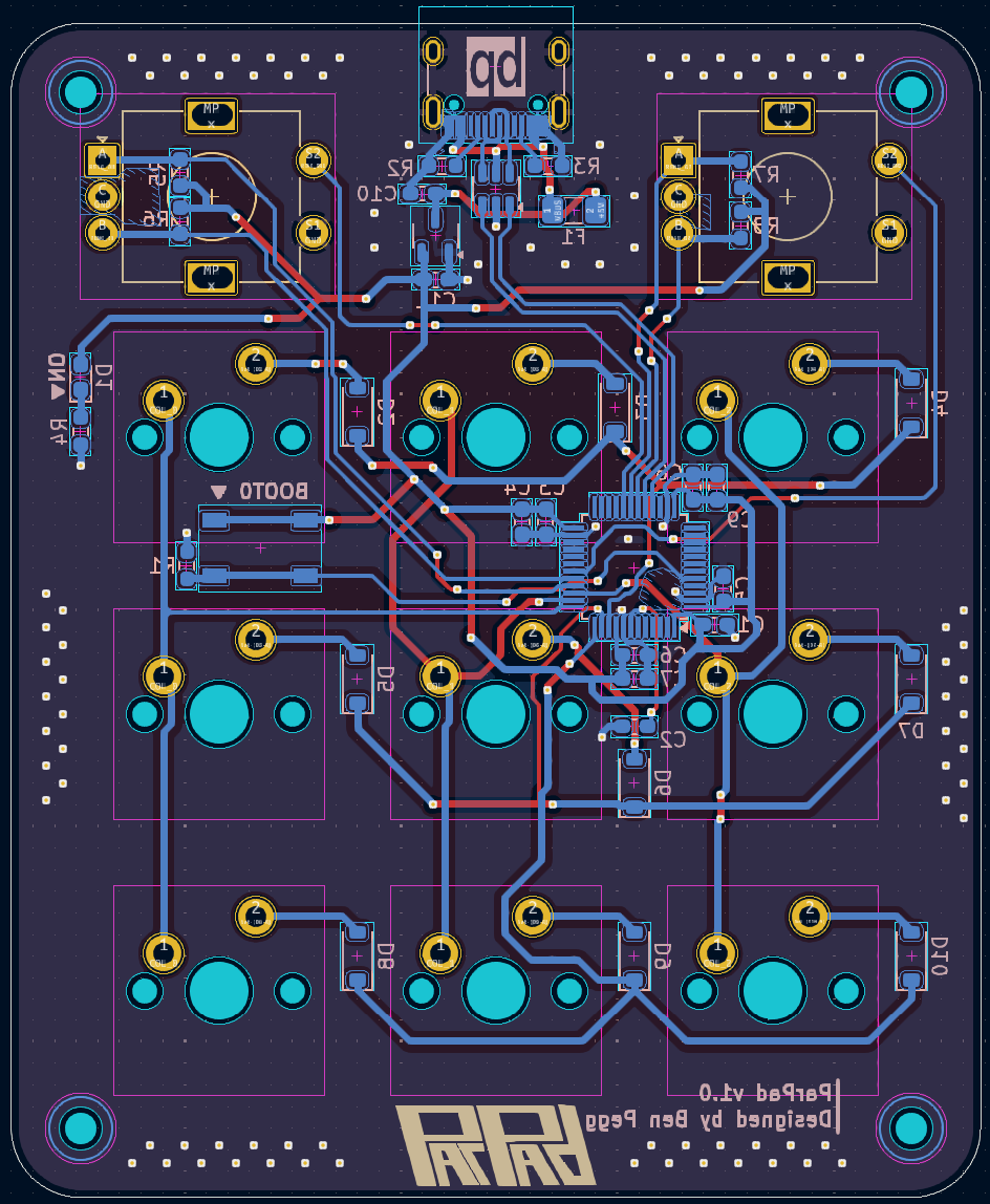
Macropad v1.0 is an open-source printed circuit board by benpegg23, from the benpegg23/ParPad repository on GitHub. It is a 2-layer board of 66.7 × 81 mm with 52 parts on 61 nets, routed with 495 tracks and 146 vias.
It is built around the STM32F072C8T6, USBLC6-2SC6 and 1N4148W. Its parts include 12 switches, 11 capacitors, 10 diodes, 8 resistors and 3 ICs. It belongs with the keyboards and input boards and the STM32 boards of this library.


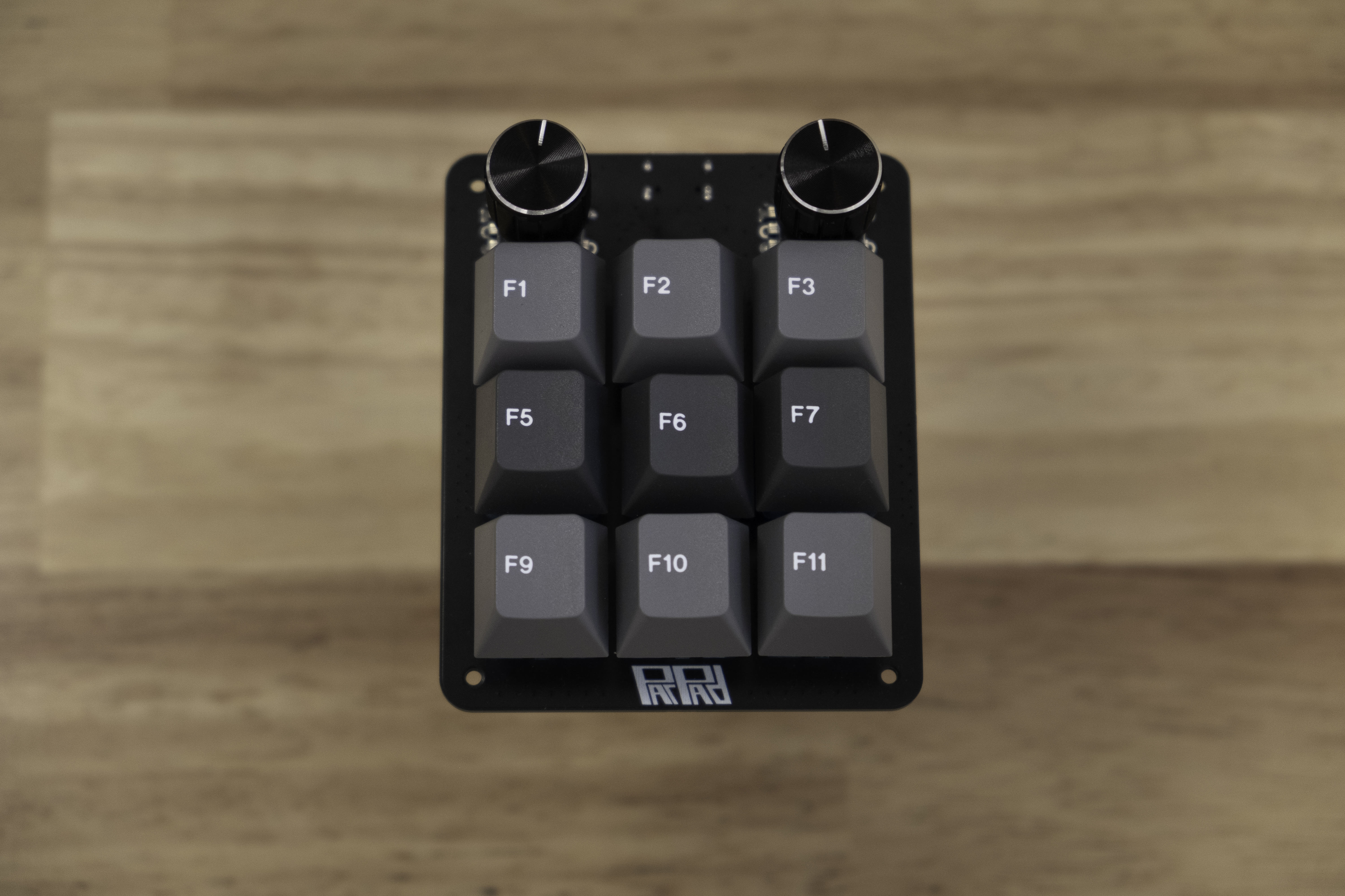
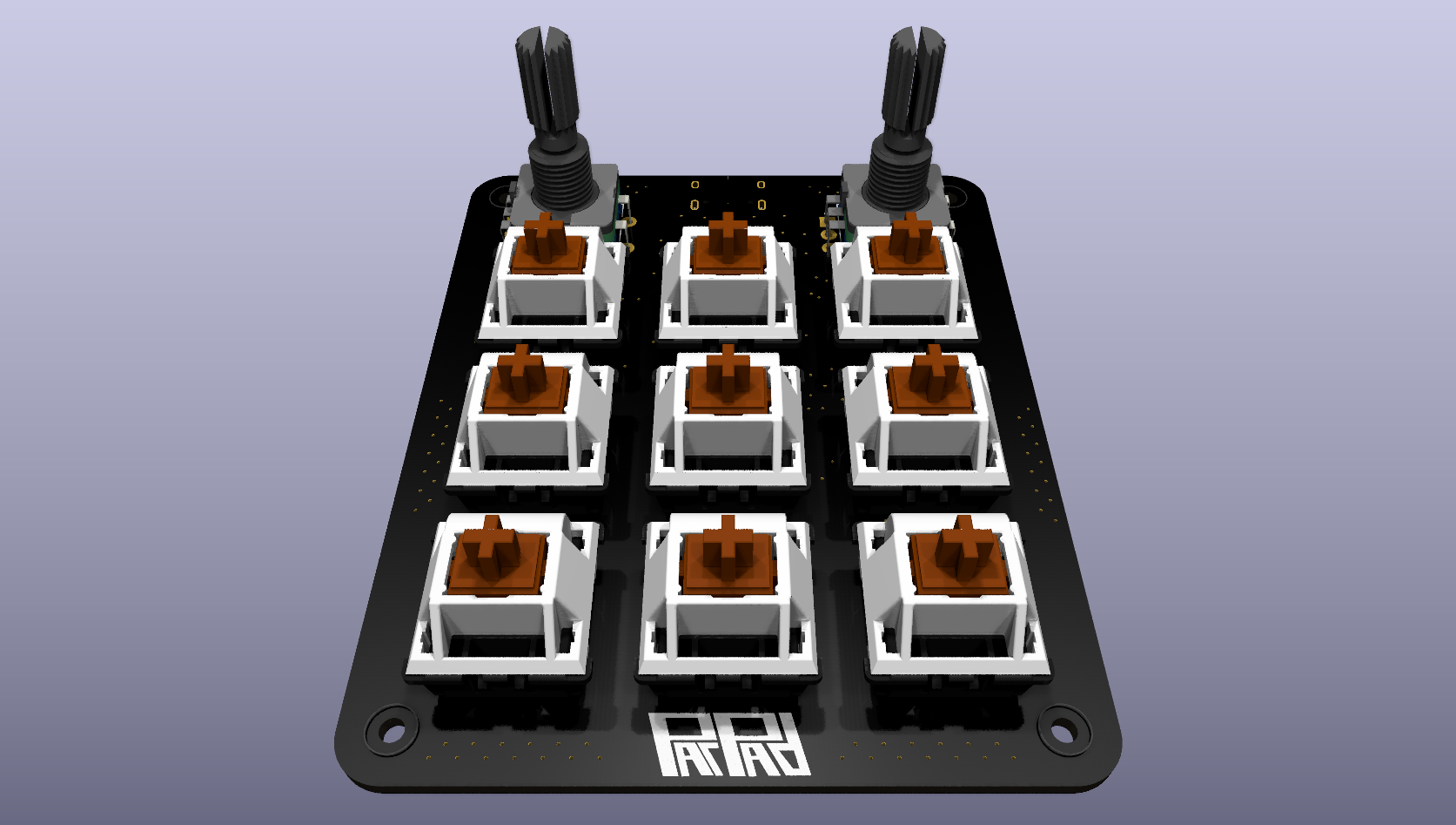
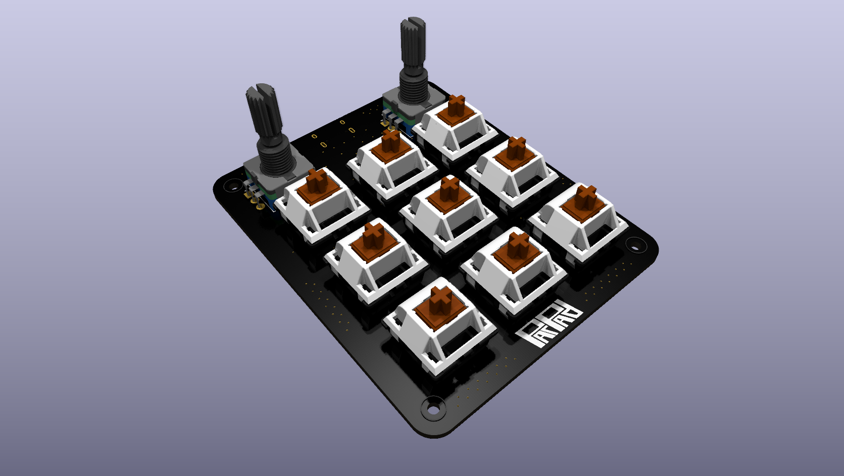
ParPad is an STM32-based macropad featuring a 3×3 layout and two rotary encoders.
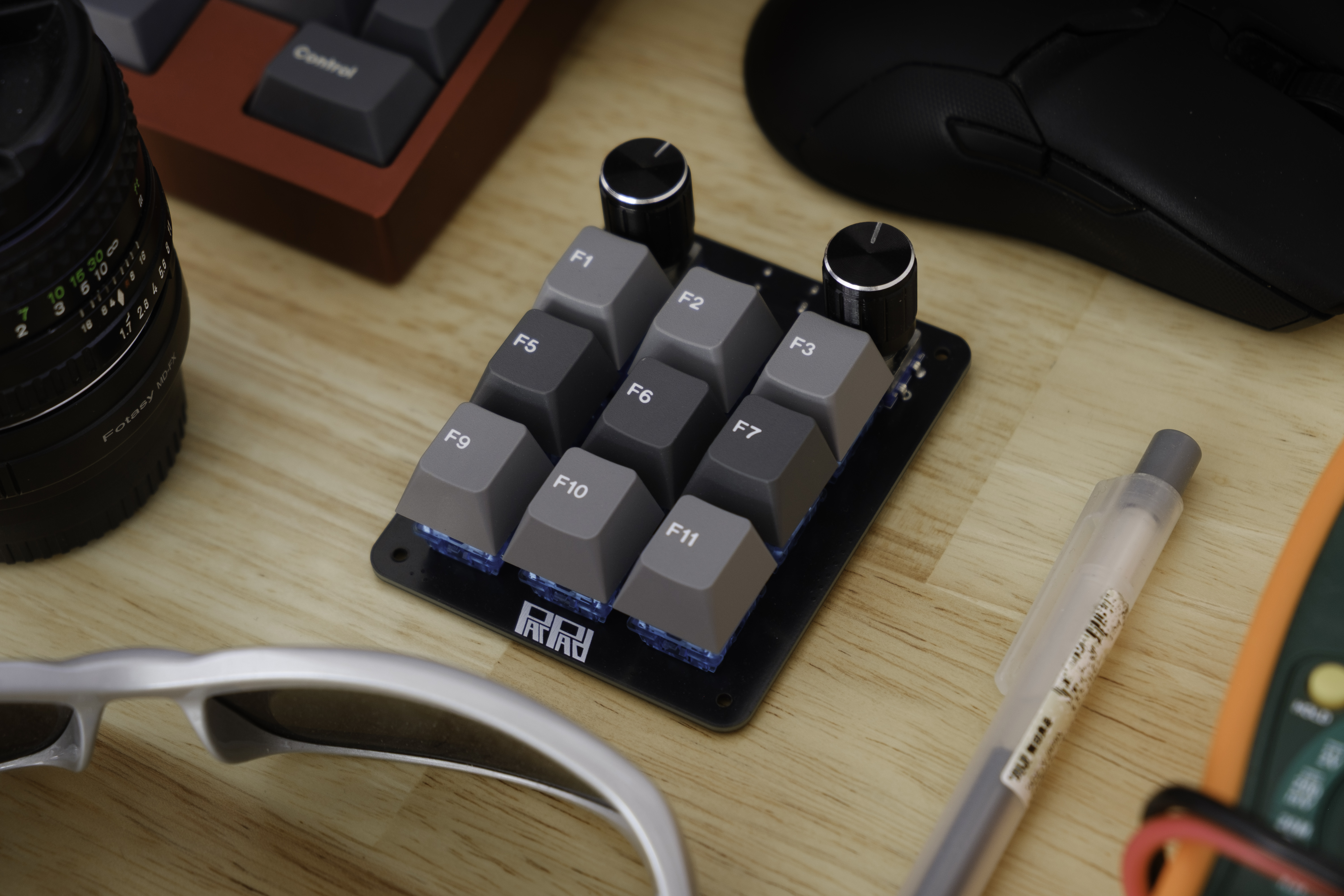
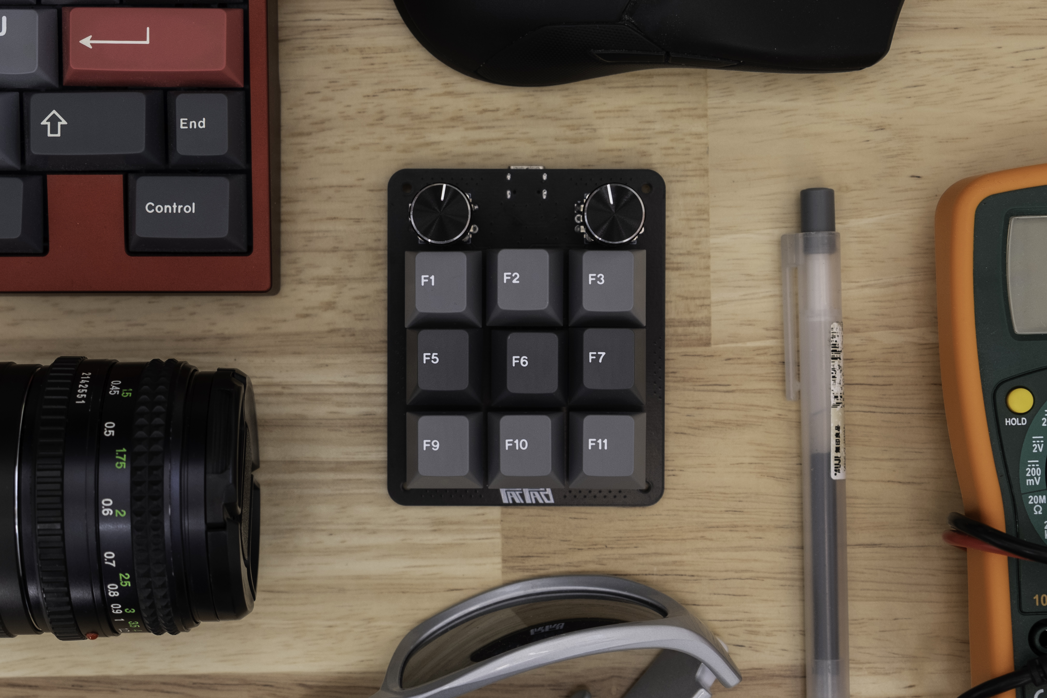
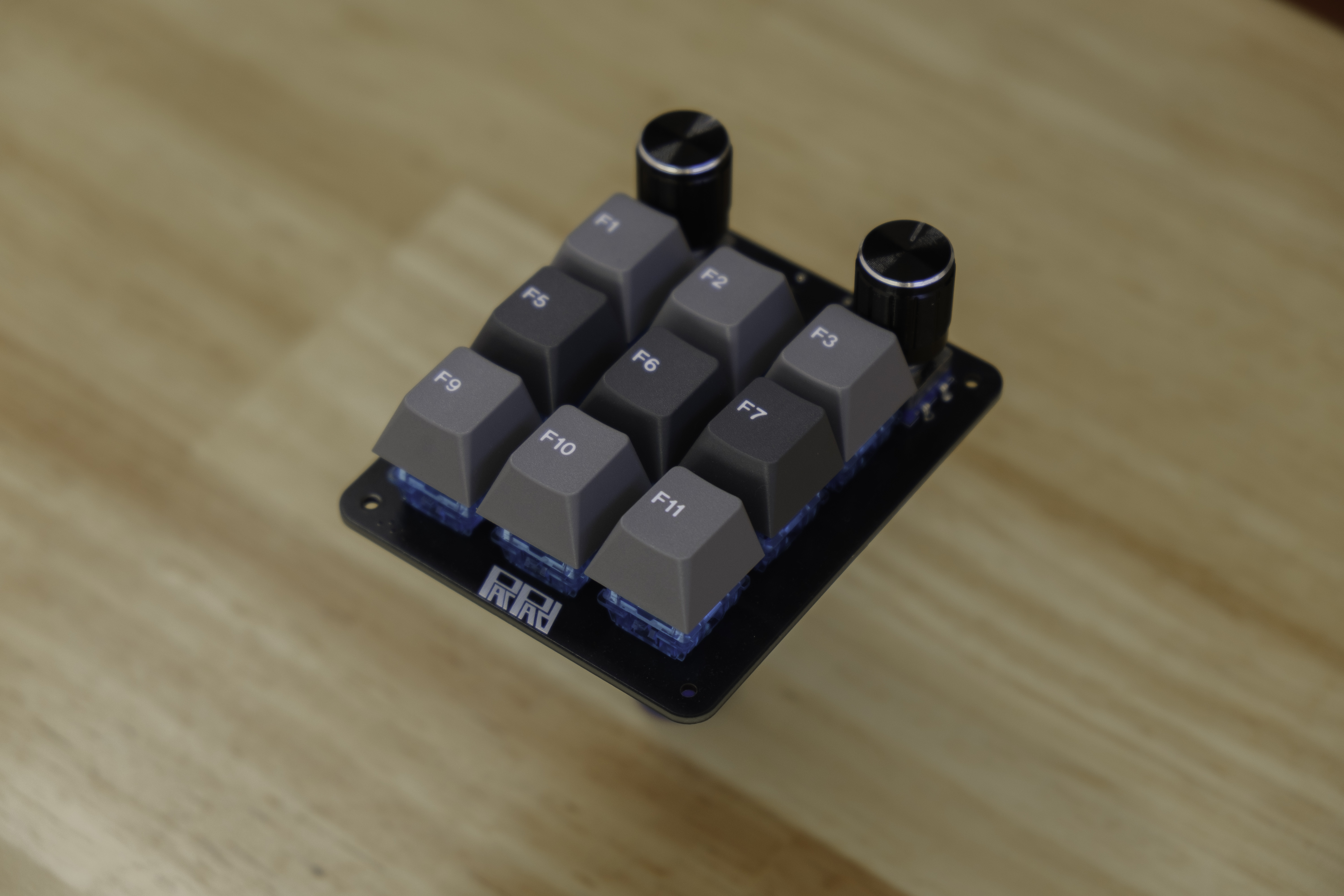
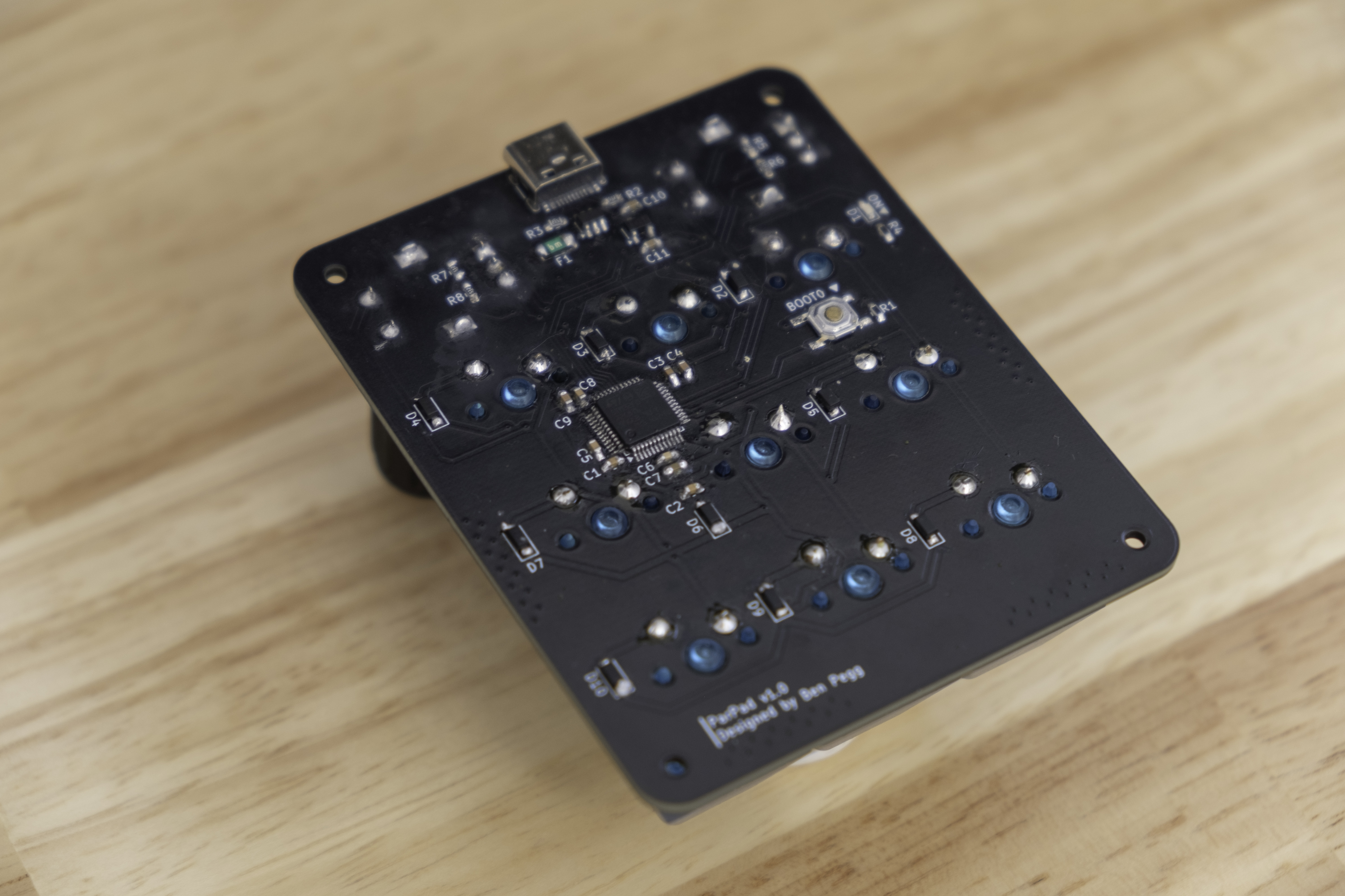
| Qty | Value | Footprint | References |
|---|---|---|---|
| 9 | 1N4148W | Diode_SMD:D_SOD-123 | D2, D3, D4, D5, D6, D7, D8, D9, D10 |
| 9 | Keyswitch | ScottoKeebs_MX:MX_PCB_1.00u | S1, S2, S3, S4, S5, S6, S7, S8, S9 |
| 6 | 5.1k | Resistor_SMD:R_0603_1608Metric_Pad0.98x0.95mm_HandSolder | R2, R3, R5, R6, R7, R8 |
| 5 | 100nF | Capacitor_SMD:C_0603_1608Metric_Pad1.08x0.95mm_HandSolder | C1, C2, C3, C5, C8 |
| 4 | MountingHole | MountingHole:MountingHole_2.2mm_M2 | H1, H2, H3, H4 |
| 3 | 1uF | Capacitor_SMD:C_0603_1608Metric_Pad1.08x0.95mm_HandSolder | C7, C10, C11 |
| 2 | 4.7uF | Capacitor_SMD:C_0603_1608Metric_Pad1.08x0.95mm_HandSolder | C4, C9 |
| 2 | LOGO | LOGO | G***, G*** |
| 2 | Rotary Encoder | Rotary_Encoder:RotaryEncoder_Alps_EC11E-Switch_Vertical_H20mm | SW2, SW3 |
| 1 | 10k | Resistor_SMD:R_0603_1608Metric_Pad0.98x0.95mm_HandSolder | R1 |
| 1 | 10nF | Capacitor_SMD:C_0603_1608Metric_Pad1.08x0.95mm_HandSolder | C6 |
| 1 | 1k | Resistor_SMD:R_0603_1608Metric_Pad0.98x0.95mm_HandSolder | R4 |
| 1 | 500mA | Fuse:Fuse_1206_3216Metric_Pad1.42x1.75mm_HandSolder | F1 |
| 1 | RED | LED_SMD:LED_0603_1608Metric_Pad1.05x0.95mm_HandSolder | D1 |
| 1 | STM32F072C8T6 | Package_QFP:LQFP-48_7x7mm_P0.5mm | U2 |
| 1 | SW_Push | ScottoKeebs_Components:Button_TL3342 | SW1 |
| 1 | USBLC6-2SC6 | Package_TO_SOT_SMD:SOT-23-6 | U1 |
| 1 | USB_C_Receptacle_USB2.0_14P | Connector_USB:USB_C_Receptacle_HRO_TYPE-C-31-M-12 | J1 |
| 1 | XC6206PxxxMR | Package_TO_SOT_SMD:SOT-23-3 | U3 |
It measures 66.7 × 81 mm and has 2 copper layers, 1.6 mm thick.
52 parts, built around the STM32F072C8T6, USBLC6-2SC6 and 1N4148W. The full list of its parts is on this page, with links to each part's symbol and footprint where PCBKit's library has them.
From the benpegg23/ParPad repository on GitHub, at the commit this page was made from: the board is hardware/macropad_v1.0/macropad_v1.0.kicad_pcb and its schematic hardware/macropad_v1.0/macropad_v1.0.kicad_sch. PCBKit opens the board in the browser, with nothing to install.
Its repository states no licence, so its author keeps all rights: ask benpegg23 before reusing the design.


meteyou/klipper-gcode-buttons
The Klipper Gcode-Buttons offer a unique control and status display solution in 3D printers and automated systems.

chapppy/Board-for-Relay-Card
Design of schematic and PCB for Relay Card control over USB and CAN based on STM32


myaki-moe/usb2can
A compact and low cost open source USB to CAN bus adaptor. 紧凑且低成本的开源USB到CAN总线适配器