
2 layers34.9 × 82.6 mm
Robot
AF-ROBOTICS/RoboticsLearningPlatform
A learning platform for various Electrical and Computer Engineering concepts and techniques.
37 parts3

A learning platform for various Electrical and Computer Engineering concepts and techniques.
Robot is an open-source printed circuit board by AF-ROBOTICS, from the AF-ROBOTICS/RoboticsLearningPlatform repository on GitHub. It is a 2-layer board of 34.9 × 82.6 mm with 34 parts on 18 nets, routed with 205 tracks and 6 vias.
It is built around the L7805 and L78L33ACU. Its parts include 8 resistors, 8 connectors, 5 capacitors, 3 transistors and 2 ICs. It belongs with the robots and motor control boards of this library.


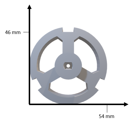
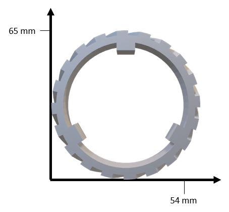
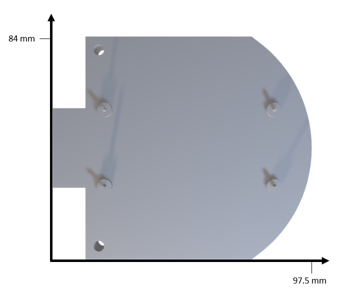
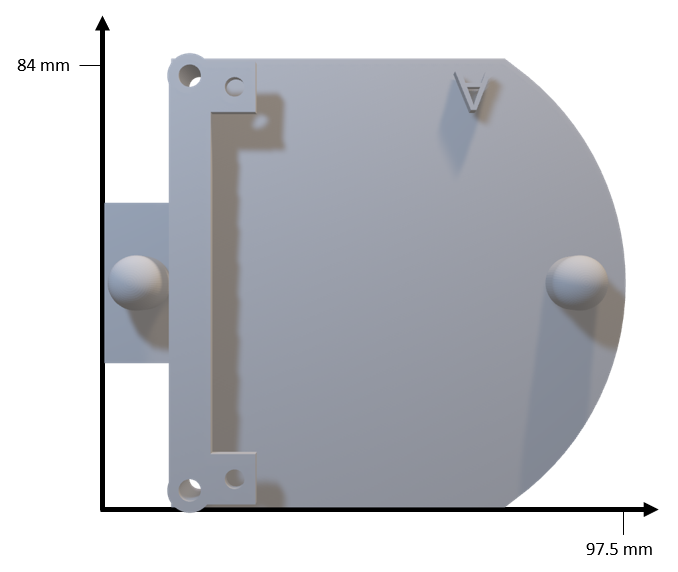
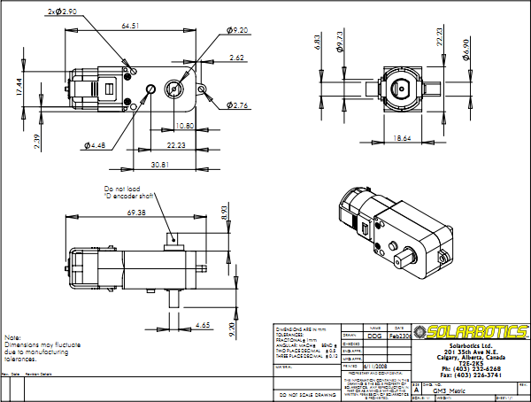
The DFEC Robot was created for the Department of Electrical and Computer Engineering (ECE) at the US Air Force Academy. It is used to teach ECE fundamentals in the major's introductory course. The robot's chassis is built using 3D printed parts. An Arduino Uno Rev3 microcontroller board and a custom designed power and motor controller Printed Circuit Board (PCB) are used to control the robot.
Six labs guide the students from soldering the PCB and assembling the robot to using distance and line sensors to guide the robot through a maze.
Robot PCB - This lab guides students to solder and test their PCB.
Robot Build - This lab provides instructions to assemble the robot.
Robot Motors - This lab investigates how the Arduino uses Pulse Width Modulation to drive the robot's motors.
Robot Drive - This lab has students control the motors to drive in specified patterns.
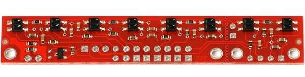
Robot Line Following - This lab integrates the Pololu QTR-8RC Line Sensor Array to enable the robot to follow a black line.
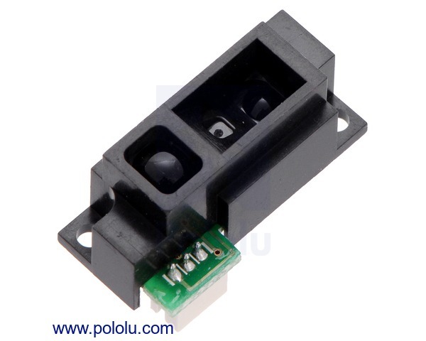
Robot Wall Following - This lab integrates the Sharp GP2Y051SK0F 2-15 cm Analog Distance Sensor to enable the robot to follow walls.
Robot Maze - This lab is broken up into three parts: 1) follow a line through a maze; 2) follow a line through a maze and turn around and return to the start of the maze; and 3) navigate a walled maze towards a goal location.
There are two custom libraries used to control the robot. These libraries should be copied into library folder at root/Documents/Arduino/libraries.
Motor - This library provides functions to drive the robot using left and right PWM values (e.g., Motor_Init(), Motor_Forward(int leftDuty, int rightDuty), and Motor_Stop())
QTR-8RC - This library is adapted from the QTRSensors library to utilize the QTR-8RC Reflectance Sensor Array to determine how far the robot is off a line.
There are several projects that incorporate the DFEC Robot into different systems. All of these are works in progress and need to be updated to utilize the new libraries.
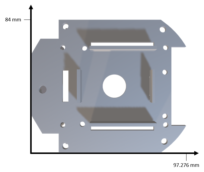
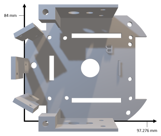
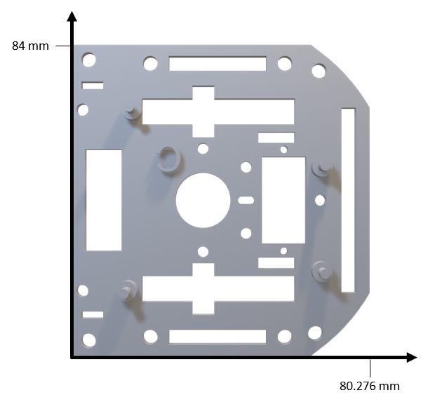
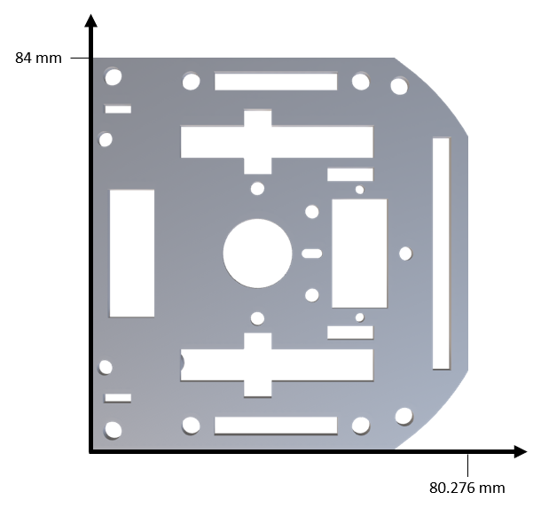
Frame developed using AutoDesk Fusion 360 and printed on a LulzBot Taz 6.
| Top | Bottom |
|---|---|
 |  |
| Top | Bottom |
|---|---|
 |  |
| Top | Bottom |
|---|---|
 |  |
| Top | Bottom |
|---|---|
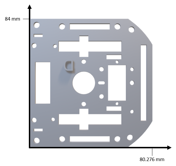 | 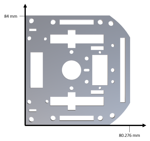 |
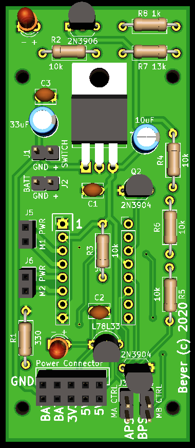 | 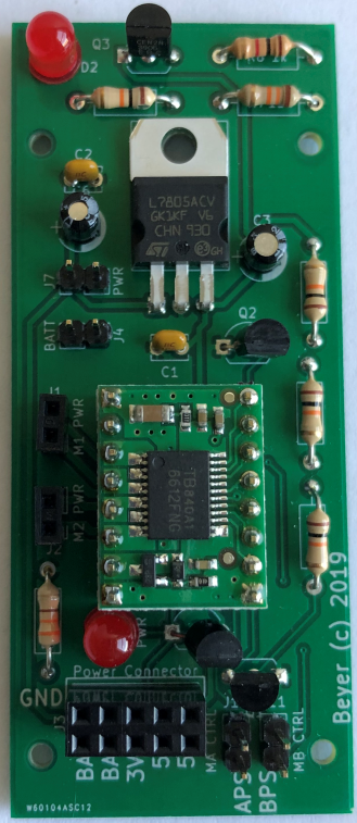 |
| Qty | Value | Footprint | References |
|---|---|---|---|
| 5 | 10k | Resistor_THT:R_Axial_DIN0207_L6.3mm_D2.5mm_P10.16mm_Horizontal | R2, R3, R4, R5, R6 |
| 4 | Mounting_Holes:MountingHole_2.2mm_M2 | , , , | |
| 3 | 0.1uF | Capacitor_THT:C_Disc_D3.8mm_W2.6mm_P2.50mm | C1, C2, C3 |
| 2 | , | ||
| 2 | - + | LED_THT:LED_D3.0mm | D1, D2 |
| 2 | 2N3904 | Package_TO_SOT_THT:TO-92L_Inline_Wide | Q1, Q2 |
| 1 | 10uF | Capacitor_THT:CP_Radial_D5.0mm_P2.00mm | C4 |
| 1 | 13k | Resistor_THT:R_Axial_DIN0207_L6.3mm_D2.5mm_P10.16mm_Horizontal | R7 |
| 1 | 1k | Resistor_THT:R_Axial_DIN0207_L6.3mm_D2.5mm_P10.16mm_Horizontal | R8 |
| 1 | 2N3906 | Package_TO_SOT_THT:TO-92_Inline_Wide | Q3 |
| 1 | 330 | Resistor_THT:R_Axial_DIN0207_L6.3mm_D2.5mm_P10.16mm_Horizontal | R1 |
| 1 | 33uF | Capacitor_THT:CP_Radial_D5.0mm_P2.00mm | C5 |
| 1 | BATT | Connector_PinHeader_2.54mm:PinHeader_1x02_P2.54mm_Vertical | J2 |
| 1 | L7805 | Package_TO_SOT_THT:TO-220-3_Horizontal_TabDown | U1 |
| 1 | L78L33 | Package_TO_SOT_THT:TO-92L_Inline_Wide | U2 |
| 1 | M1 PWR | Connector_PinSocket_2.54mm:PinSocket_1x02_P2.54mm_Vertical | J5 |
| 1 | M2 PWR | Connector_PinSocket_2.54mm:PinSocket_1x02_P2.54mm_Vertical | J6 |
| 1 | MA CTRL | Connector_PinHeader_2.54mm:PinHeader_1x02_P2.54mm_Vertical | J3 |
| 1 | MB CTRL | Connector_PinHeader_2.54mm:PinHeader_1x02_P2.54mm_Vertical | J4 |
| 1 | Power Connector | Connector_PinSocket_2.54mm:PinSocket_2x05_P2.54mm_Vertical | J7 |
| 1 | SWITCH | Connector_PinHeader_2.54mm:PinHeader_1x02_P2.54mm_Vertical | J1 |
| 1 | TB6612_Motor_Driver | bob:Pololu_TB6612 | J8 |
It measures 34.9 × 82.6 mm and has 2 copper layers, 1.6 mm thick.
34 parts, built around the L7805 and L78L33ACU. The full list of its parts is on this page, with links to each part's symbol and footprint where PCBKit's library has them.
From the AF-ROBOTICS/RoboticsLearningPlatform repository on GitHub, at the commit this page was made from: the board is PCB/pcb_v2/robot.kicad_pcb. PCBKit opens the board in the browser, with nothing to install.
Its repository states no licence, so its author keeps all rights: ask AF-ROBOTICS before reusing the design.
AF-ROBOTICS/RoboticsLearningPlatform
A learning platform for various Electrical and Computer Engineering concepts and techniques.

AF-ROBOTICS/RoboticsLearningPlatform
A learning platform for various Electrical and Computer Engineering concepts and techniques.

AF-ROBOTICS/RoboticsLearningPlatform
A learning platform for various Electrical and Computer Engineering concepts and techniques.

AF-ROBOTICS/RoboticsLearningPlatform
A learning platform for various Electrical and Computer Engineering concepts and techniques.


Ausdauersportler/IMAC-EFI-BOOT-SCREEN
How to create an EFI boot screen vBIOS for Apple Late 2009 to Mid 2011 iMac systems using AMD MXM graphics cards

joyel24/CheapMesh
PCB for Heltec HT-CT62: ESP32-C3 + SX1262 lora cheap module. Useful to run MeshTastic. Forked from : https://gitlab.com/paulhausk/CheapMesh


wbommel/iot-telemetry-scale-pcb
This repository contains the KiCAD design files for the custom PCB used in the IoT Telemetry Scale project – a modular, networked weighing solution originally built to monitor the weights of budgies in an aviary. 🐦📡

