2 layers192.2 × 150.5 mm

 aewtemp/rpi-energy-meter
Additionally, the board incorporates transformers to step down the mains voltage to a measurable level for voltage monitoring. Caution: This board operates with potentially dangerous voltages.
RPiWattMeterHatv3 is an open-source printed circuit board by aewtemp, from the aewtemp/rpi-energy-meter repository on GitHub. It is a 2-layer board of 99.9 × 91 mm with 70 parts on 64 nets, routed with 556 tracks and 33 vias.
It is built around the MCP3008-I/P, LMV321 and 160D20. Its parts include 26 capacitors, 26 resistors, 7 ICs and 5 connectors.


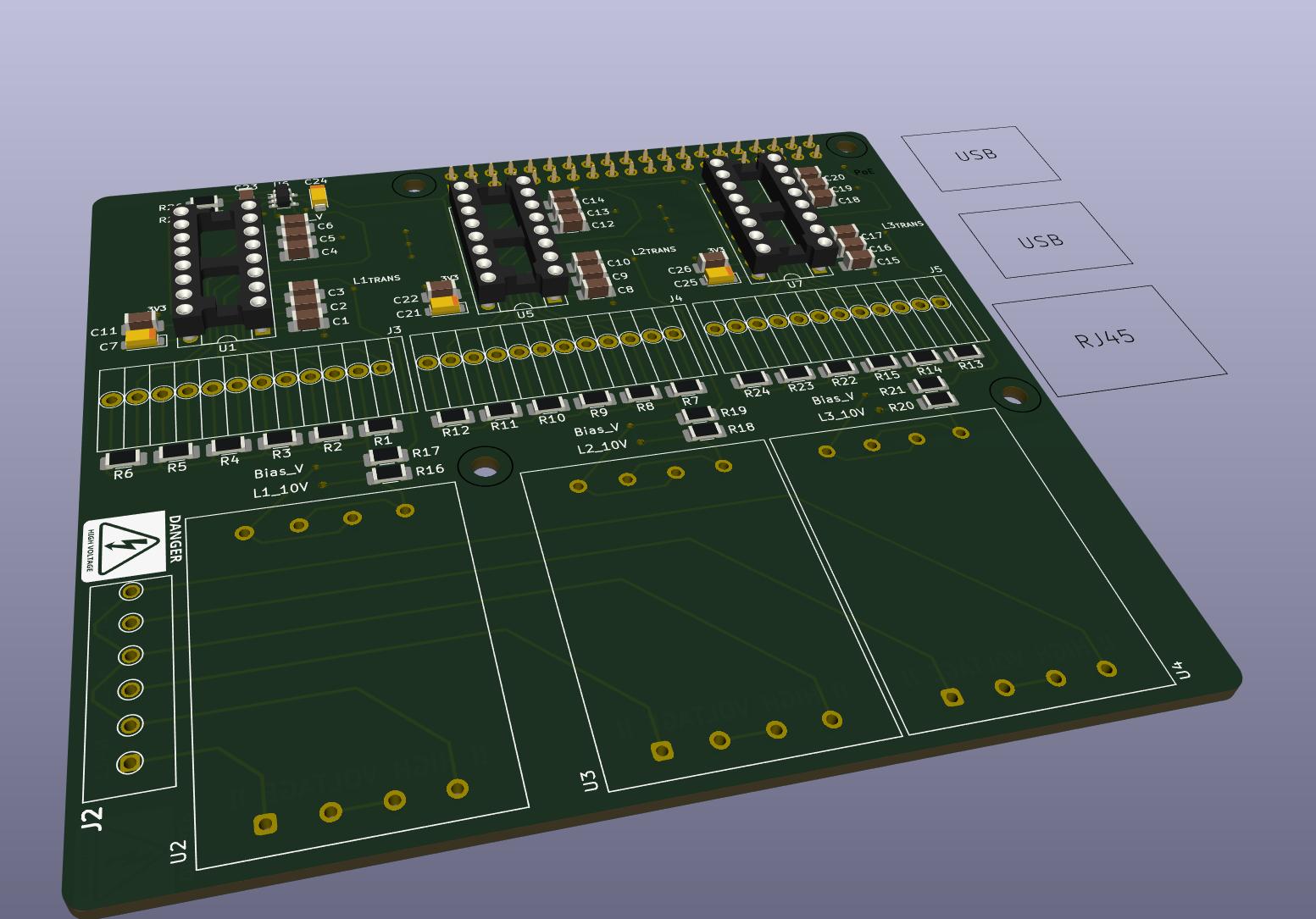
This PCB is designed for measuring electrical current across three phases, with 6 individual channels per phase. Each channel represents a separate current path and uses current transformers (CTs) for sensing. The board uses 22 Ohm burden resistors for each CT channel.
Additionally, the board incorporates transformers to step down the mains voltage to a measurable level for voltage monitoring. Caution: This board operates with potentially dangerous voltages. There is no touch protection, and improper handling may result in electric shock.
This is a DIY project and comes with no warranty or guarantee of safety or performance. Use at your own risk.
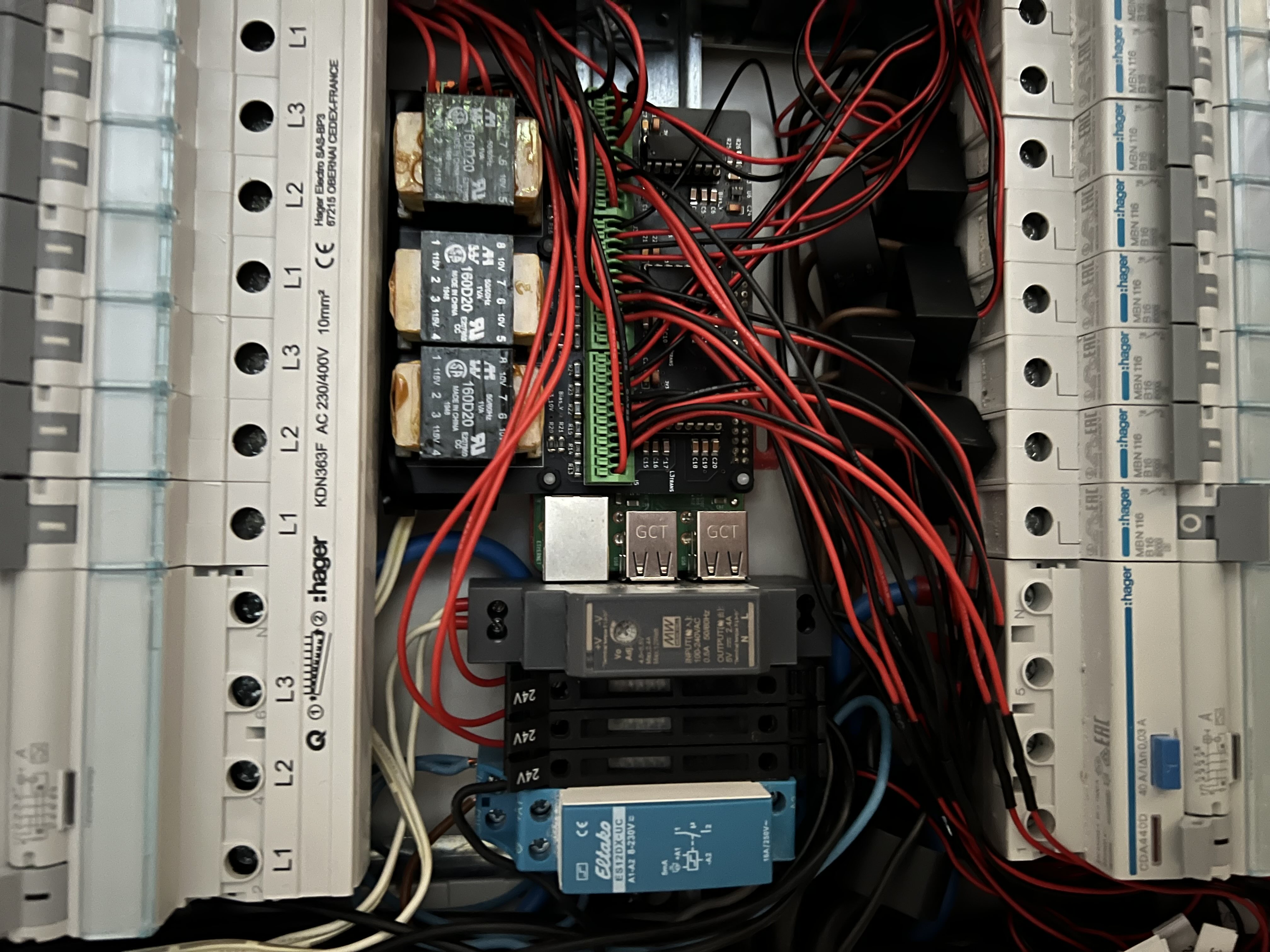
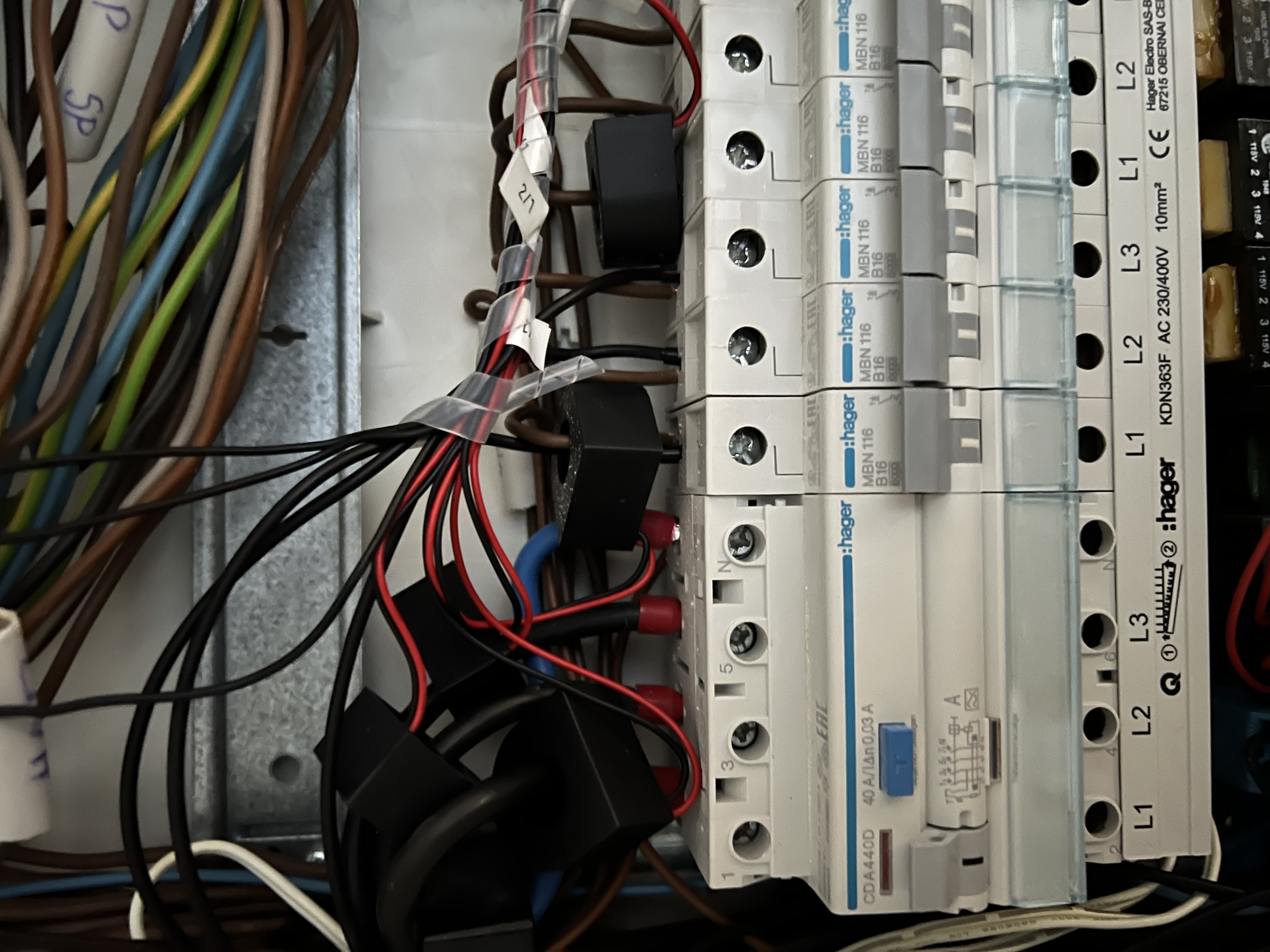
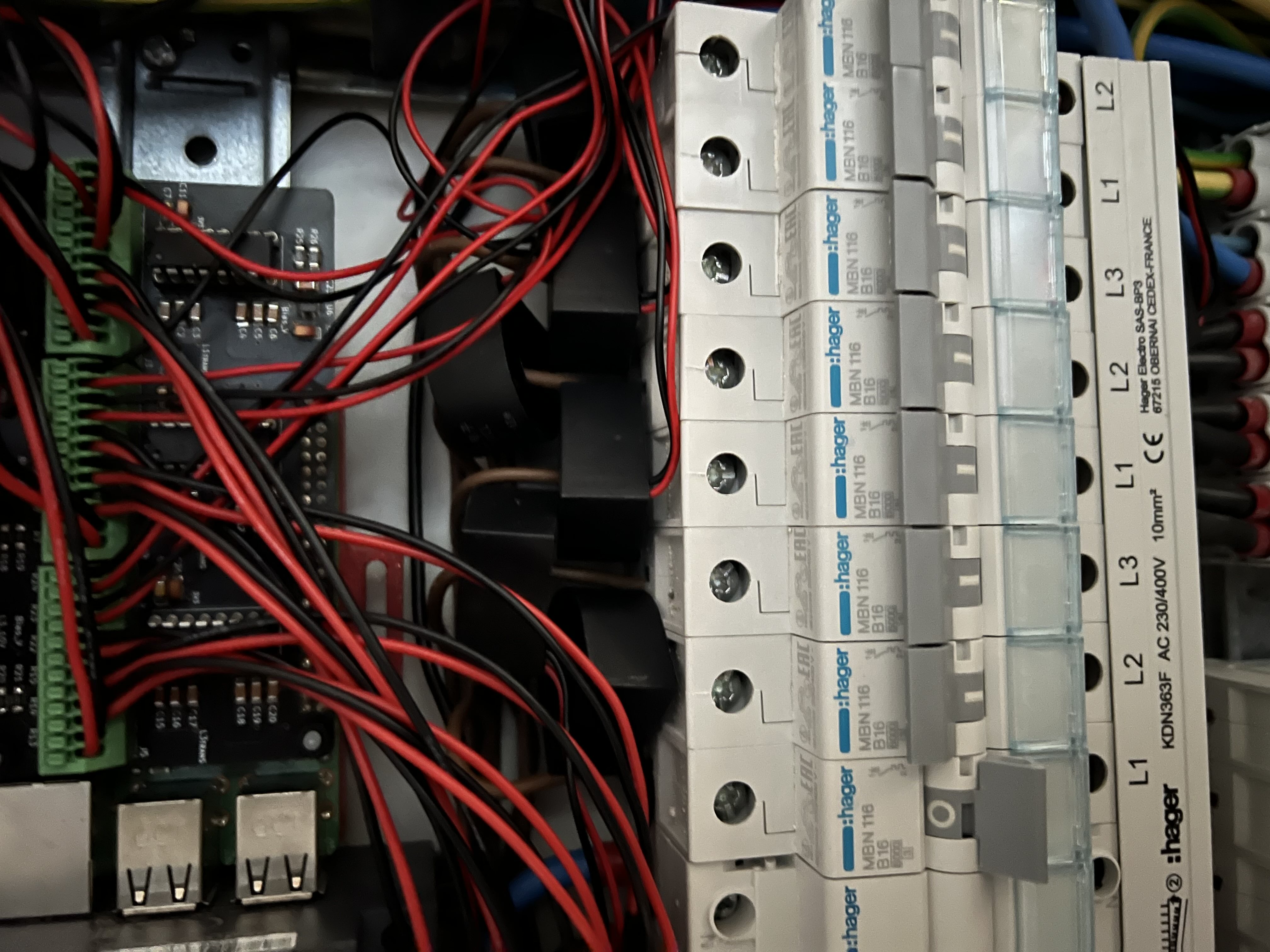
I personally have this setup running now for 2 years.
| Qty | Value | Footprint | References |
|---|---|---|---|
| 18 | 10nF | Capacitor_SMD:C_1206_3216Metric_Pad1.33x1.80mm_HandSolder | C1, C2, C3, C4, C5, C6, C10, C12, C13, C14, C15, C16, C17, C18, C19, C20 +2 |
| 18 | 22R | Resistor_SMD:R_1206_3216Metric_Pad1.30x1.75mm_HandSolder | R1, R2, R3, R4, R5, R6, R7, R10, R11, R12, R13, R14, R15, R22, R23, R24 +2 |
| 4 | MountingHole_2.7mm_M2.5 | MountingHole:MountingHole_2.7mm_M2.5 | MH1, MH2, MH3, MH4 |
| 3 | 100k | Resistor_SMD:R_1206_3216Metric_Pad1.30x1.75mm_HandSolder | R16, R18, R20 |
| 3 | 100nF | Capacitor_SMD:C_1206_3216Metric_Pad1.33x1.80mm_HandSolder | C11, C22, C26 |
| 3 | 10k | Resistor_SMD:R_1206_3216Metric_Pad1.30x1.75mm_HandSolder | R17, R19, R21 |
| 3 | 160D20 | RPiWattMeterFootprints:Hammond_160D20 | U2, U3, U4 |
| 3 | 220uF | Capacitor_Tantalum_SMD:CP_EIA-3216-12_Kemet-S_Pad1.58x1.35mm_HandSolder | C7, C21, C25 |
| 3 | MCP3008 | Package_DIP:DIP-16_W7.62mm_Socket | U1, U5, U7 |
| 3 | Screw_Terminal_01x12 | RPiWattMeterFootprints:PhoenixContact_PTSA 0,5_12-2,5-F | J3, J4, J5 |
| 2 | 12k | Resistor_SMD:R_1206_3216Metric_Pad1.30x1.75mm_HandSolder | R25, R26 |
| 2 | LOGO | RPiWattMeterFootprints:schem_high_voltage | G***, G*** |
| 1 | 100nF | Capacitor_Tantalum_SMD:CP_EIA-3216-12_Kemet-S_Pad1.58x1.35mm_HandSolder | C24 |
| 1 | 1uF | Capacitor_SMD:C_1206_3216Metric_Pad1.33x1.80mm_HandSolder | C23 |
| 1 | GPIO | Connector_PinSocket_2.54mm:PinSocket_2x20_P2.54mm_Vertical | J1 |
| 1 | LMV321 | Package_TO_SOT_SMD:SOT-23-5 | U6 |
| 1 | Screw_Terminal_01x06 | RPiWattMeterFootprints:PhoenixContact_1891108 | J2 |

0x23/nmWave-Interferometer
An Open Source Interferometer for Accurate Distance Measurements

KarlK90/yaemk-split-kb
5x8 Split keyboard with thumb-clusters, rotary encoders and oleds.

lucysrausch/sony-scopeman
Hardware Design files of a replacement mainboard for the Sony Watchman FD-10. This turns it into a bluetooth and WiFi-enabled vector display.


luftaquila/monolith
DIY wireless real-time datalogging platform for Student Formula and Baja.


Kaleidogeist/Cantaloupe
~60% QMK-compatible Split Ergonomic Keyboard
It measures 99.9 × 91 mm and has 2 copper layers, 1.6 mm thick.
70 parts, built around the MCP3008-I/P, LMV321 and 160D20. The full list of its parts is on this page, with links to each part's symbol and footprint where PCBKit's library has them.
From the aewtemp/rpi-energy-meter repository on GitHub, at the commit this page was made from: the board is PCB/RPiWattMeterHatv3.kicad_pcb and its schematic PCB/RPiWattMeterHatv3.kicad_sch. PCBKit opens the board in the browser, with nothing to install.
Its repository states no licence, so its author keeps all rights: ask aewtemp before reusing the design.