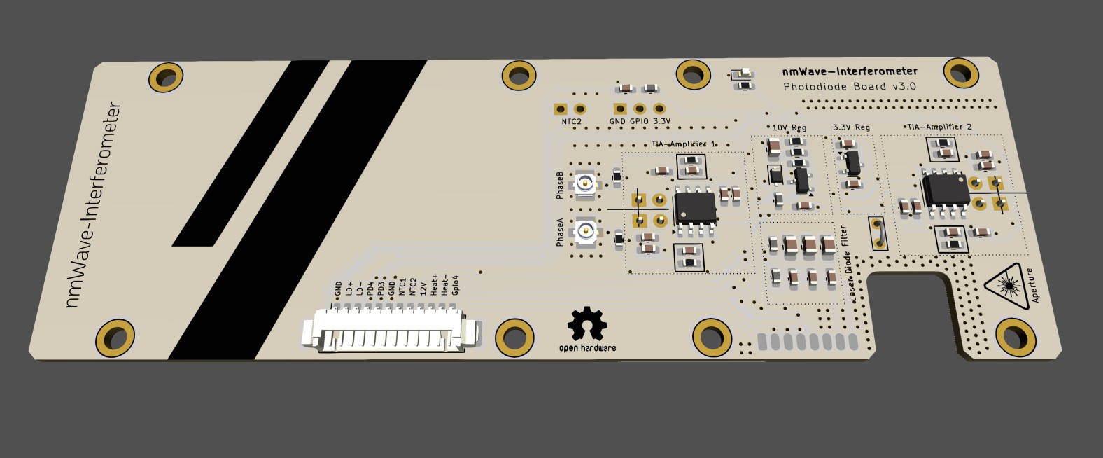
2 layers40 × 120 mm
Photodiode board v3
0x23/nmWave-Interferometer
An Open Source Interferometer for Accurate Distance Measurements
65 parts151MIT
 0x23/nmWave-Interferometer151
An Open Source Interferometer for Accurate Distance Measurements
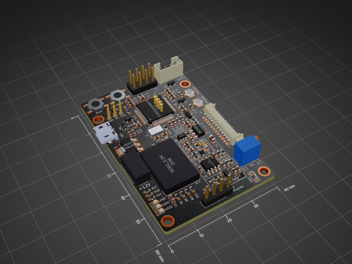
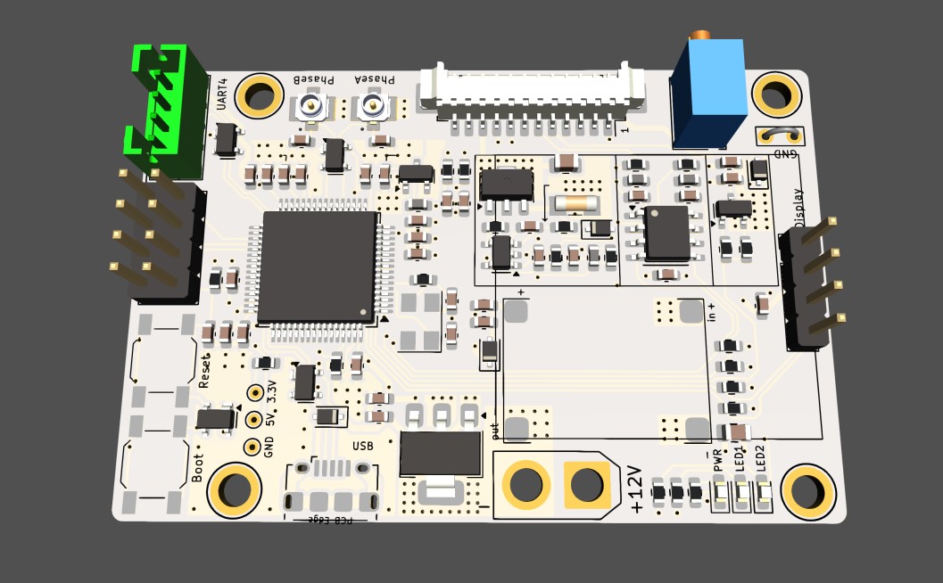
Control board v2.0 is an open-source printed circuit board by 0x23, from the 0x23/nmWave-Interferometer repository on GitHub, published under the MIT licence. It is a 4-layer board of 40 × 60 mm with 106 parts on 85 nets, routed with 740 tracks and 251 vias.
It is built around the LMV321, PMEG4010CEJ and PRTR5V0U2X, with the BCX56 and IRLML6244 among its other parts. Its parts include 35 capacitors, 22 resistors, 11 diodes, 8 connectors and 6 ICs. It belongs with the STM32 boards of this library.


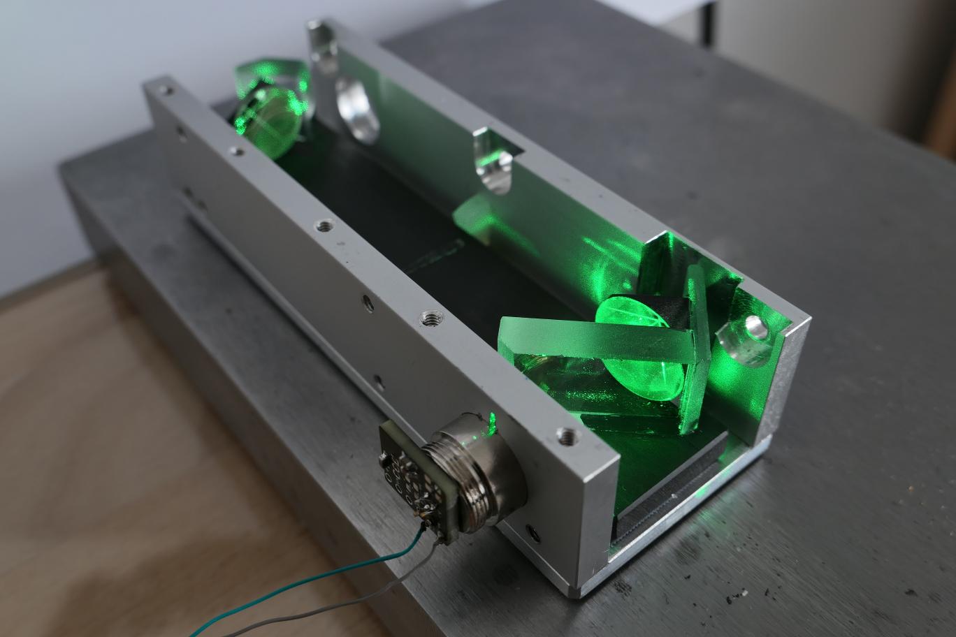
The goal of this project is to provide plans and techniques for building an interferometer that can accurately measure changes in distance over a range of hundreds of millimeters with sub-micrometer precision. The objective is to use low-cost, widely available components and achieve a good balance between ease of manufacturing and performance.
This repository is currently work in progress...
[!WARNING]
This project involves collimated laser beams with power levels above eye-safe limits able to cause permanent eye damage. Please use proper precautions, do your own research, and respect laser safety guidelines.
The KICAD design files for the electronics have been updated to the newest development version. The design is still work in progress but all functions have been successfully tested on a prototype.
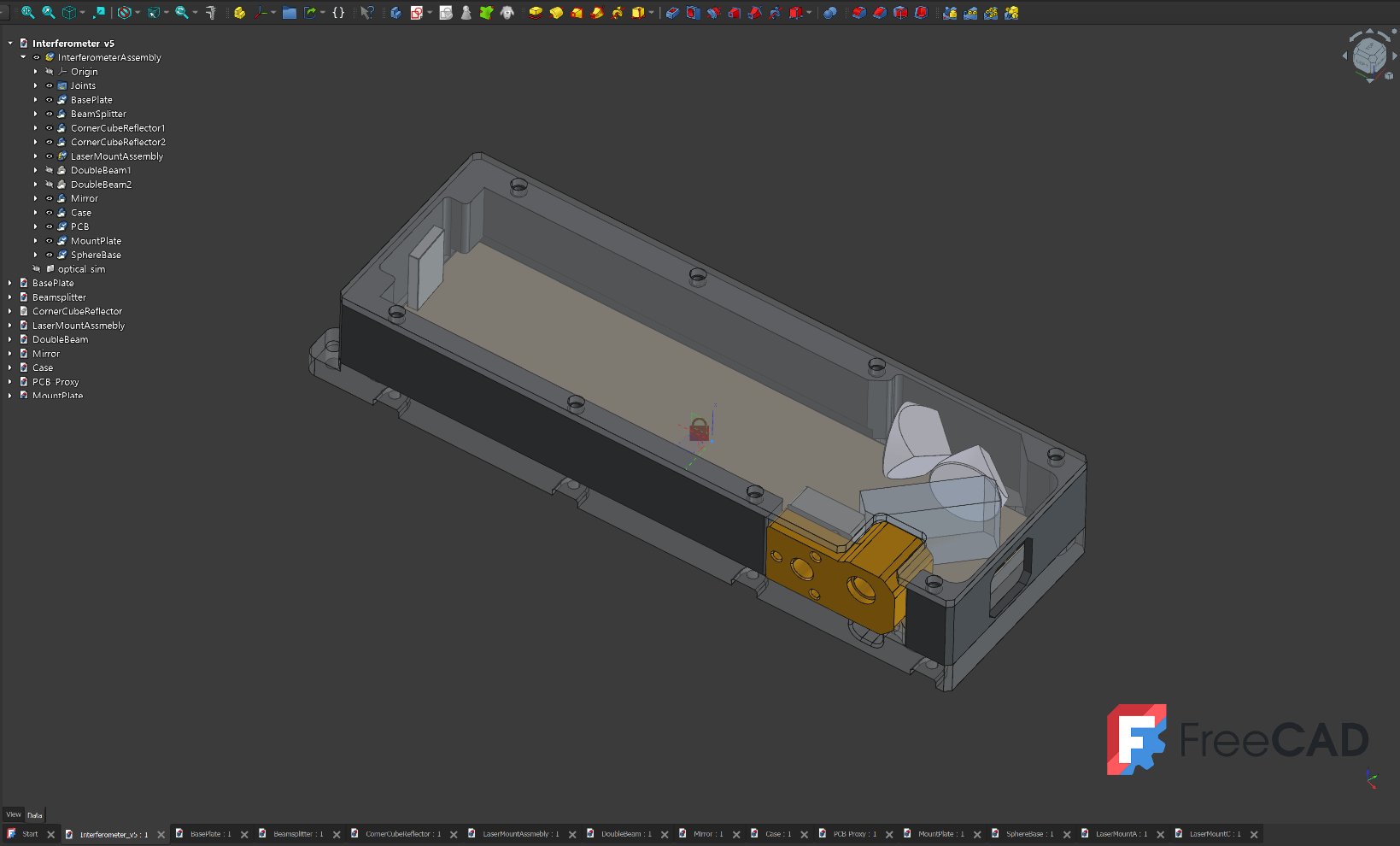
[NEW DESIGN - Version 5] FreeCAD models of the design are now online, take a look!
The Beam splitter is made from regular float glass with a thickness of about 6 mm. It does not requre any coatings and uses the inherent reflectivity of glass surfaces. It is ground to size using a diamond wetstone and a series of 3D printed jigs. The models for 3d printing can be found here:
The current recommandation is the: $${\color{lightgreen}Osram \space PLT5 \space 516FA}$$ costing about 12$
For this project the laser source requires a long coherence length, which only certain laser diode models can provide.
Below is a table of laser diodes that I tested or want to test in future:
| Part Number | Nominal Current | Optimal Drive Current | Power | Wavelength | Notes | Plus on case |
|---|---|---|---|---|---|---|
| SLD3232VF | 55mA | ? | 50mW | 405nm | Not good | Yes |
| QL65E7SA | 50mA | 30mA | 7mW | 650nm | Good | Yes |
| QL65E7SB or C | 50mA | 30mA | 7mW | 650nm | Good | Yes |
| PLT520B | 225mA | ? | 110mW | 520nm | Very good (coherence length >4m) | Yes |
| PLT5 516FA | 100mA | 36mA | 30mW | 516nm | (Very) good (CURRENT CHOICE) | No |
| PLT5 520EB_Q | - | ? | 20mW | 520nm | Not tested (datasheet suggests very good) | No |
| PLT5 450(G)B | 80mA | 21mA | 100mW | 450nm | Okay | No |
| PLT5 520DB | - | ? | 10mW | 520nm | Not tested (probably not good) | No |
| PLT5 518FB_P | - | ? | 30mW | 518nm | Not tested (probably not good) | No |
For the project fast photodiodes for the visible spectral range are required. Silicon PIN Photodiodes satisfy these requirements and are readily available. To get a good signal a small active area of about 1mm² without a lens is prefereable.
The current choice is the $${\color{lightgreen}SFH229}$$ photodiode in a 3mm LED casing costing about 0.70$.
It is sensitive in the range of 380 nm bis 1100 nm and has a switching time of 10ns. To to reduce the footprint and remove the lense a 3D printed jig and sandpaper can be used. Mor information on this subject is coming soon..
| Qty | Value | Footprint | References |
|---|---|---|---|
| 15 | 0.1µF | Capacitor_SMD:C_0603_1608Metric | C4, C7, C10, C14, C15, C16, C17, C19, C22, C24, C26, C28, C31, C34, C35 |
| 8 | 10µF | Capacitor_SMD:C_0603_1608Metric | C3, C5, C6, C8, C11, C12, C13, C18 |
| 5 | 10K | Resistor_SMD:R_0603_1608Metric | R4, R7, R11, R17, R18 |
| 4 | 100pF | Capacitor_SMD:C_0603_1608Metric | C9, C27, C32, C33 |
| 4 | 1µF | Capacitor_SMD:C_0603_1608Metric | C20, C21, C23, C25 |
| 4 | 4K7 | Resistor_SMD:R_0603_1608Metric | R8, R9, R14, R15 |
| 4 | FerriteBead | Inductor_SMD:L_0603_1608Metric | FB1, FB2, FB3, FB4 |
| 4 | MountingHole | MountingHole:MountingHole_2.7mm_M2.5_ISO14580_Pad | H1, H2, H3, H4 |
| 4 | PMEG4010CEJ | Diode_SMD:D_SOD-323F | D1, D2, D3, D8 |
| 4 | PRTR5V0U2X | Package_TO_SOT_SMD:SOT-143 | D5, D9, D10, D11 |
| 3 | 1.5k | Resistor_SMD:R_0603_1608Metric | R20, R21, R22 |
| 3 | LED | LED_SMD:LED_0603_1608Metric_Pad1.05x0.95mm_HandSolder | D4, D6, D7 |
| 3 | TestPoint | TestPoint:TestPoint_THTPad_D1.0mm_Drill0.5mm | TP5, TP6, TP7 |
| 2 | 100K | Resistor_SMD:R_0603_1608Metric | R10, R13 |
| 2 | 10µF, 16V | Capacitor_SMD:C_0805_2012Metric | C1, C2 |
| 2 | 15pF | Capacitor_SMD:C_0603_1608Metric | C29, C30 |
| 2 | 33k | Resistor_SMD:R_0603_1608Metric | R12, R19 |
| 2 | MHF_SMD | ConMFH_SMD:LINX_CONMHF1-SMD-T | J3, J8 |
| 1 | 0 | Resistor_SMD:R_0603_1608Metric | R16 |
| 1 | 10 | Resistor_SMD:R_MiniMELF_MMA-0204 | R5 |
| 1 | 100k | Resistor_SMD:R_0603_1608Metric | R2 |
| 1 | 10k | Resistor_SMD:R_0603_1608Metric | R1 |
| 1 | 12V | Connector_AMASS:AMASS_XT30U-F_1x02_P5.0mm_Vertical | J1 |
| 1 | 1k | Resistor_SMD:R_0603_1608Metric | R3 |
| 1 | 2K | Potentiometer_THT:Potentiometer_Bourns_3266X_Horizontal | RV1 |
| 1 | 3.3K | Resistor_SMD:R_0603_1608Metric | R6 |
| 1 | BCX56 | Package_TO_SOT_SMD:SOT-89-3 | Q1 |
| 1 | Conn_PDBoard | Connector_Molex:Molex_PicoBlade_53261-1271_1x12-1MP_P1.25mm_Horizontal | J5 |
| 1 | DCDC_3.3V | DCDC_Converter:DCDC_17mmx12mm | U2 |
| 1 | Display | Connector_PinHeader_2.54mm:PinHeader_1x04_P2.54mm_Vertical | J2 |
| 1 | IRLML6244 | Package_TO_SOT_SMD:SOT-23 | Q2 |
| 1 | LMV321 | Package_TO_SOT_SMD:SOT-23-5 | U3 |
| 1 | MCP1700x-300xxTT | Package_TO_SOT_SMD:SOT-23 | U1 |
| 1 | MCP1825S | Package_TO_SOT_SMD:SOT-223-3_TabPin2 | U4 |
| 1 | MCP3426Axx-xSN | Package_SO:SOIC-8_3.9x4.9mm_P1.27mm | U5 |
| 1 | MJ-12.000-33412 | Crystal:Crystal_SMD_5032-4Pin_5.0x3.2mm | Y1 |
| 1 | PA0 | TestPoint:TestPoint_THTPad_D1.0mm_Drill0.5mm | TP1 |
| 1 | PC1 | TestPoint:TestPoint_THTPad_D1.0mm_Drill0.5mm | TP2 |
| 1 | PC2 | TestPoint:TestPoint_THTPad_D1.0mm_Drill0.5mm | TP3 |
| 1 | PC3 | TestPoint:TestPoint_THTPad_D1.0mm_Drill0.5mm | TP4 |
| 1 | PRMG | Connector_PinHeader_2.54mm:PinHeader_2x04_P2.54mm_Vertical | J7 |
| 1 | STM32G431RBTx | Package_QFP:LQFP-64_10x10mm_P0.5mm | U6 |
| 1 | SW_Boot | Button_Switch_SMD:SW_SPST_SKQG_WithoutStem | SW2 |
| 1 | SW_Reset | Button_Switch_SMD:SW_SPST_SKQG_WithoutStem | SW1 |
| 1 | TestPoint | TestPoint:TestPoint_Bridge_Pitch2.54mm_Drill0.7mm | TP8 |
| 1 | UART1 | Connector_JST:JST_PH_B4B-PH-K_1x04_P2.00mm_Vertical | J4 |
| 1 | USB_B_Micro | Connector_USB:USB_Micro-B_Amphenol_10118194_Horizontal | J6 |
The 104 most common of 106 parts.
0x23/nmWave-Interferometer
An Open Source Interferometer for Accurate Distance Measurements

0x23/nmWave-Interferometer
An Open Source Interferometer for Accurate Distance Measurements


DoImant/TP4056-Power-Path-PCB
TP4056 Power Sharing PCB. Charge battery despite connected load.


0x23/BallJointEmbossingMachine
A motorized linear embossing machine designed to precisely press ball joints. It was designed to automate the production of balljoint linkages for the Open-Micro-Manipulator.

It measures 40 × 60 mm and has 4 copper layers, 1.6 mm thick.
106 parts, built around the LMV321, PMEG4010CEJ, PRTR5V0U2X and BCX56. The full list of its parts is on this page, with links to each part's symbol and footprint where PCBKit's library has them.
From the 0x23/nmWave-Interferometer repository on GitHub, at the commit this page was made from: the board is electronics/control_board_v2.0/control_board_v2.0.kicad_pcb and its schematic electronics/LaserDiodeBoard_v2/LaserDiodeBoard_v2.kicad_sch. PCBKit opens the board in the browser, with nothing to install.
Its repository publishes it under the MIT licence: you may reuse it on that licence's terms (keep the author's notice, and for a copyleft licence share your changes alike).