

2 layers23 × 120 mm

This is a research project. We are planning to make an open source dataset of Bengali Sign Language (BdSL). To collect data of hand movements we are creating this smart glove for both hand using esp32, MPU650 and 3d printed flex sensors.
Glove is an open-source printed circuit board by Adnanosman9, from the Adnanosman9/Smart-Gloves repository on GitHub, published under the MIT licence. It is a 2-layer board of 38.5 × 34.5 mm with 16 parts on 34 nets, routed with 107 tracks and 12 vias.
It is built around the MPU-6050. Its parts include 7 resistors, 5 connectors, 2 capacitors and 2 ICs. It belongs with the ESP32 and RISC-V boards of this library.
The BdSL Translator Glove is a wearable device designed to translate BdSL into words without any camera setup.
Shoutout to zackfreedman for the original parametric ring glove concept that inspired this design. You can grab my modified STL here.
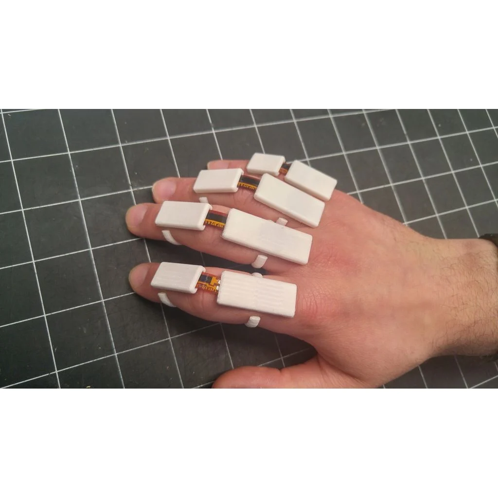
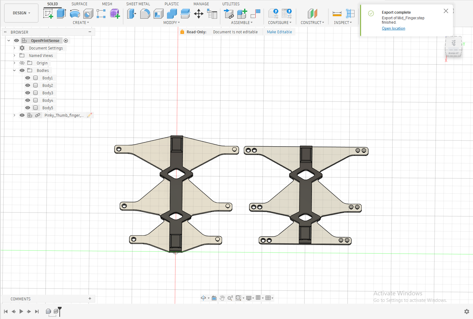
Instead of messing around with messy glues or tape, each finger uses a 3D-printed TPU channel segment where the sensor just slides right in and locks mechanically. I split these into two sizes:
Any standard FDM printing service can easily run these off in white TPU filament.
I put together a compact wrist hub in KiCad to keep the electronics tidy. A few design choices:
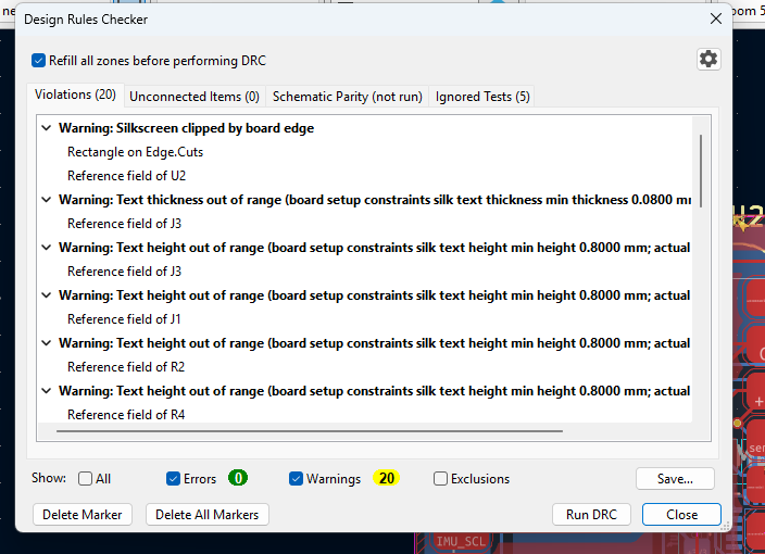
The KiCad DRC checked out cleanly with 0 errors (just a few minor silkscreen overlap warnings that won't disrupt manufacturing).
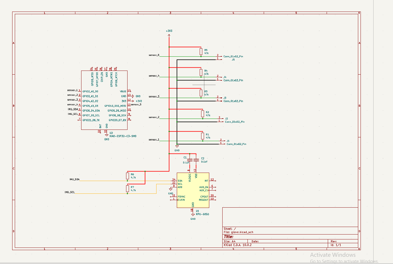
Schematic:
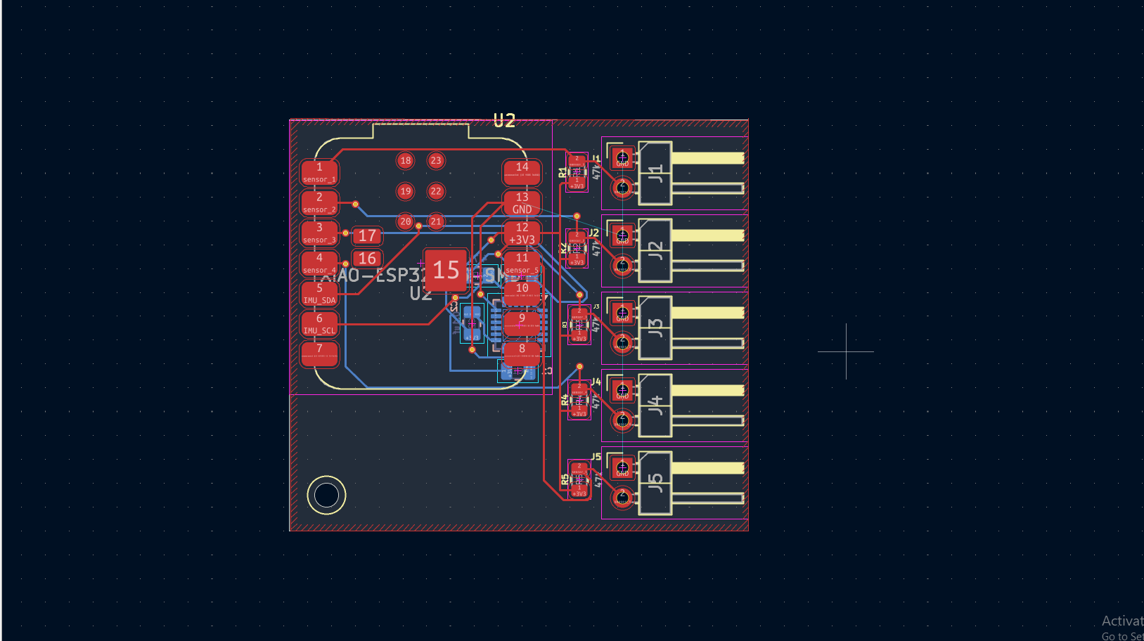
PCB Layout:
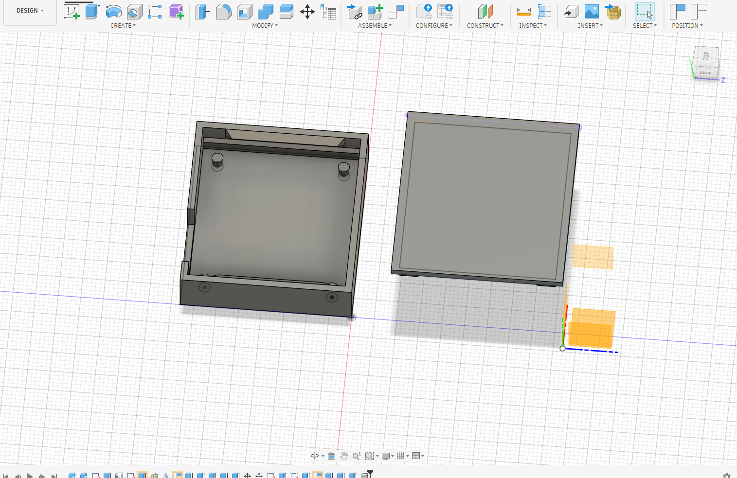
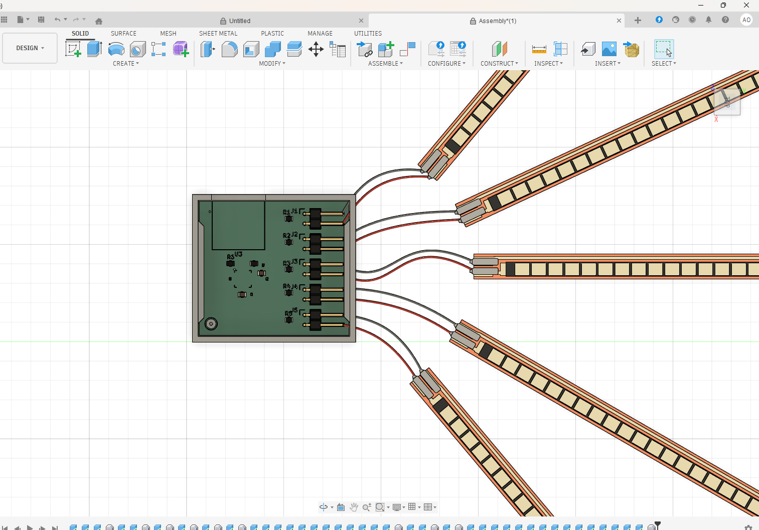
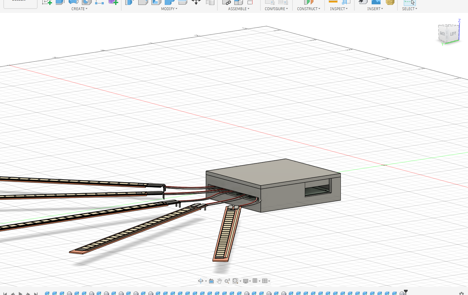
The wrist housing was designed in Fusion 360 to keep the pcb safe.
Here is an alter for commercial sensors for cost optimization.
Just a quick heads up: I haven't been able to run this code on physical hardware yet. It's highly likely there are some I2C pin configuration mismatches, flipped GPIO definitions, or sensor initialization bugs waiting to happen on the first boot. Please double-check your schematic assignments against your software configuration before flashing!
You can view the full parts list in the BOM file here.
GitHub @Adnanosman
| Qty | Value | Footprint | References |
|---|---|---|---|
| 5 | 47k | Resistor_SMD:R_0805_2012Metric | R1, R2, R3, R4, R5 |
| 5 | Conn_01x02_Pin | Connector_PinHeader_2.54mm:PinHeader_1x02_P2.54mm_Horizontal | J1, J2, J3, J4, J5 |
| 2 | 0.1uf | Capacitor_SMD:C_0805_2012Metric | C1, C2 |
| 2 | 4.7k | Resistor_SMD:R_0805_2012Metric | R6, R7 |
| 1 | MPU-6050 | Sensor_Motion:InvenSense_QFN-24_4x4mm_P0.5mm | U1 |
| 1 | XIAO-ESP32-C3-SMD | RF_Module:MCU_Seeed_ESP32C3 | U2 |

ZhuYanzhen1/MM32_CLion
本项目是全国大学生智能车竞赛GDUT 2022年极速越野组的项目文件。采用了LQR控制器和多速率卡尔曼融合算法,并在单片机上实现。This project is the project document for the GDUT 2022 Extreme Off-Road Category of the National Student Intelligent Vehicle Competition.


victorhook/asac-fc
asac fc is an rp2040 based flight controller made for FPV drone flying


pms67/PModlet
PMOD PCB with USB-to-UART converter and IMU (MPU-6050, I2C) for FPGAs.
It measures 38.5 × 34.5 mm and has 2 copper layers, 1.6 mm thick.
16 parts, built around the MPU-6050. The full list of its parts is on this page, with links to each part's symbol and footprint where PCBKit's library has them.
From the Adnanosman9/Smart-Gloves repository on GitHub, at the commit this page was made from: the board is PCB/glove.kicad_pcb and its schematic PCB/glove.kicad_sch. PCBKit opens the board in the browser, with nothing to install.
Its repository publishes it under the MIT licence: you may reuse it on that licence's terms (keep the author's notice, and for a copyleft licence share your changes alike).