
2 layers26 × 30 mm
Microcontroller
FrameworkComputer/ExpansionCards
Reference designs and documentation to create Expansion Cards for the Framework Laptop
34 parts1.1kCC-BY-4.0

 adhyayan15/orion1-pcb
Version 1 of Orion, a custom STM32-based robotics controller PCB designed in KiCad.
Orion-1 is an open-source printed circuit board by adhyayan15, from the adhyayan15/orion1-pcb repository on GitHub, published under the MIT licence. It is a 2-layer board of 101.6 × 101.6 mm with 42 parts on 107 nets, routed with 818 tracks and 74 vias.
It is built around the AP2112K-3.3. Its parts include 10 resistors, 9 capacitors, 2 ICs, 2 connectors and 1 switch. It belongs with the robots and motor control boards and the STM32 boards of this library.
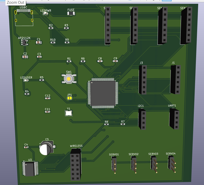
I wanted a controller I could eventually use in my own robots instead of building every project around a development board and a mess of jumper wires. That's where Orion-1 started.
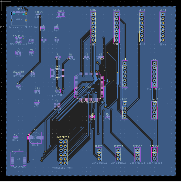
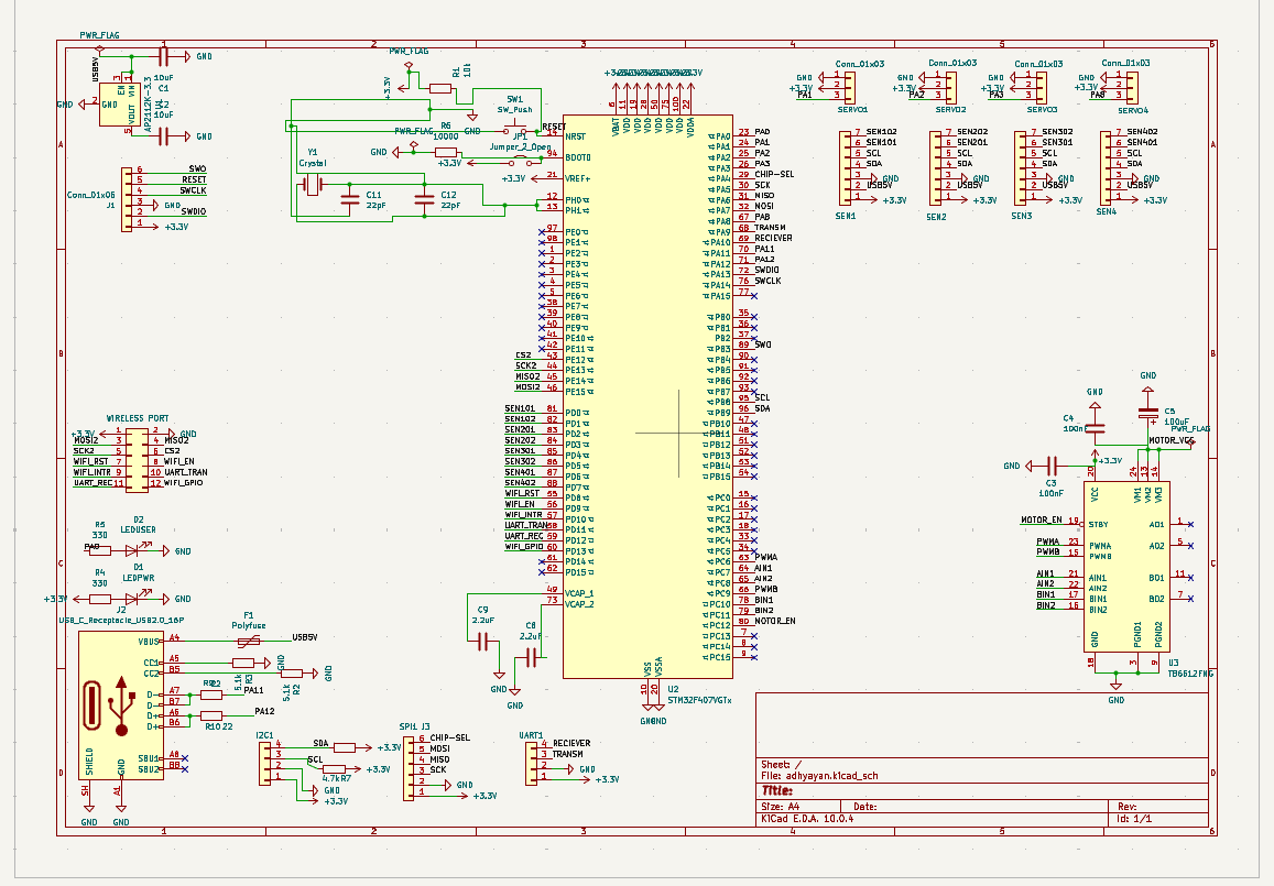
The plan was to put the essentials on one PCB: an STM32, motor control, servo connections, power regulation, and enough headers to plug in sensors later. I built the schematic and laid out the board in KiCad. It's a 4 × 4-inch, two-layer design based around the STM32F407VGTx.
This is revision one, not a finished commercial controller. Some functional issues are still unresolved, and I haven't documented a successful full hardware bring-up. I'm keeping it here because the design process itself taught me a lot.
| Part | Why it's there |
|---|---|
| STM32F407VGTx | Main microcontroller; an Arm Cortex-M4 |
| TB6612FNG | Dual DC-motor driver |
| AP2112K-3.3 | 3.3 V regulation for the logic side |
| USB-C connector + polyfuse | Part of the input/power interface |
| Four servo headers | Connections for future actuators |
| UART, I²C, SPI and sensor headers | Room to add peripherals |
| SWD signals, reset, oscillator, LEDs | Bring-up, debugging and basic feedback |
The KiCad project uses a 101.6 × 101.6 mm, two-copper-layer board outline, with 1.6 mm nominal thickness.
| PCB layout | Schematic |
|---|---|
 |  |
The parts list was the easy part. Getting all those parts to make sense together was harder.
I spent time sorting out KiCad's power flags and ERC messages, thinking through the USB supply path, checking crystal connections, and fixing grounding and routing issues. A robotics board also forces you to think about things you can mostly ignore on a breadboard: motor current, where the return paths go, and whether your connectors will actually be usable after assembly.
One thing I would do differently is plan the bring-up process earlier, before worrying so much about making the layout look finished. A routed board isn't the same thing as a tested board.
The repository includes the editable KiCad project, exported Gerber layers, and the images above. It's still a design-stage prototype. I haven't included firmware, measured rail voltages, or a verified motor/servo demo. The current repository also doesn't have NC drill output, so the manufacturing package needs to be regenerated before ordering.
If you're looking through the design, the most useful files are:
I want to resolve the electrical issues, verify the 3.3 V supply and SWD connection, flash a basic LED test, and then move on to peripherals and motor control. Once I can show actual measurements and a running board, I'll add them here rather than just calling the design “working.”
Built by Adhyayan Tiwari · MIT License
| Qty | Value | Footprint | References |
|---|---|---|---|
| 4 | Conn_01x03 | Connector_PinHeader_2.54mm:PinHeader_1x03_P2.54mm_Vertical | SERVO1, SERVO2, SERVO3, SERVO4 |
| 2 | 100nF | Capacitor_SMD:C_0603_1608Metric | C3, C4 |
| 2 | 10uF | Capacitor_SMD:C_0805_2012Metric | C1, C2 |
| 2 | 2.2uF | Capacitor_SMD:C_0603_1608Metric_Pad1.08x0.95mm_HandSolder | C8, C9 |
| 2 | 22 | Resistor_SMD:R_0603_1608Metric | R9, R10 |
| 2 | 22pF | Capacitor_SMD:C_0603_1608Metric_Pad1.08x0.95mm_HandSolder | C11, C12 |
| 2 | 330 | Resistor_SMD:R_0603_1608Metric | R4, R5 |
| 2 | 4.7k | Resistor_SMD:R_0603_1608Metric | R7, R8 |
| 2 | 5.1k | Resistor_SMD:R_0603_1608Metric | R2, R3 |
| 2 | ~ | Connector_PinSocket_2.54mm:PinSocket_1x04_P2.54mm_Vertical | I2C1, UART1 |
| 1 | 10000 | Resistor_SMD:R_0603_1608Metric | R6 |
| 1 | 100uF | Capacitor_SMD:CP_Elec_6.3x5.4 | C5 |
| 1 | 10k | Resistor_SMD:R_0603_1608Metric | R1 |
| 1 | AP2112K-3.3 | Package_TO_SOT_SMD:SOT-23-5 | AP2112K |
| 1 | Conn_01x06 | Connector_PinSocket_2.54mm:PinSocket_1x06_P2.54mm_Vertical | J1 |
| 1 | Crystal | Crystal:Crystal_SMD_3225-4Pin_3.2x2.5mm | Y1 |
| 1 | Jumper_2_Open | Jumper:SolderJumper-2_P1.3mm_Open_RoundedPad1.0x1.5mm | JP1 |
| 1 | LEDPWR | LED_SMD:LED_0603_1608Metric | LEDPWR |
| 1 | LEDUSER | LED_SMD:LED_0603_1608Metric | LEDUSER |
| 1 | Polyfuse | Fuse:Fuse_1206_3216Metric | FUSE |
| 1 | SEN1 | Connector_PinSocket_2.54mm:PinSocket_1x07_P2.54mm_Vertical | SEN1 |
| 1 | SEN2 | Connector_PinSocket_2.54mm:PinSocket_1x07_P2.54mm_Vertical | SEN2 |
| 1 | SEN3 | Connector_PinSocket_2.54mm:PinSocket_1x07_P2.54mm_Vertical | SEN3 |
| 1 | SEN4 | Connector_PinSocket_2.54mm:PinSocket_1x07_P2.54mm_Vertical | SEN4 |
| 1 | SPI1 | Connector_PinSocket_2.54mm:PinSocket_1x06_P2.54mm_Vertical | J3 |
| 1 | STM32F407VGTx | Package_QFP:LQFP-100_14x14mm_P0.5mm | U2 |
| 1 | SW_Push | Button_Switch_SMD:SW_SPST_TL3342 | SW1 |
| 1 | TB6612FNG | Package_SO:SSOP-24_5.3x8.2mm_P0.65mm | U3 |
| 1 | USB_C_Receptacle_USB2.0_16P | Connector_USB:USB_C_Receptacle_HRO_TYPE-C-31-M-12 | USBC |
| 1 | WIRELESS PORT | Connector_PinSocket_2.54mm:PinSocket_2x06_P2.54mm_Vertical | WIRELESS |
FrameworkComputer/ExpansionCards
Reference designs and documentation to create Expansion Cards for the Framework Laptop


DDeGonge/OS-ARM
This arm is not industrial and it will not be fast, but that is not my goal. But it will hopefully be a very nice looking arm fully capable of 6dof motion, cheap enough to keep it accessable but capable enough to…


It measures 101.6 × 101.6 mm and has 2 copper layers, 1.6 mm thick.
42 parts, built around the AP2112K-3.3. The full list of its parts is on this page, with links to each part's symbol and footprint where PCBKit's library has them.
From the adhyayan15/orion1-pcb repository on GitHub, at the commit this page was made from: the board is KiCad/orion-1.kicad_pcb and its schematic KiCad/orion-1.kicad_sch. PCBKit opens the board in the browser, with nothing to install.
Its repository publishes it under the MIT licence: you may reuse it on that licence's terms (keep the author's notice, and for a copyleft licence share your changes alike).