

4 layers71.1 × 99.1 mm

 adhyayan15/BCD_Decade_Counter
Designed a custom KiCad PCB for a BCD decade counter, transitioning a verified breadboard prototype into a manufacturable circuit.
BCD Decade Counter is an open-source printed circuit board by adhyayan15, from the adhyayan15/BCD_Decade_Counter repository on GitHub, published under the MIT licence. It is a 2-layer board of 129.5 × 33 mm with 15 parts on 24 nets, routed with 122 tracks and 1 via.
It is built around the HDSP-7503 and NE555P. Its parts include 9 resistors, 4 ICs, 1 capacitor and 1 connector.
A breadboard circuit I turned into a PCB to get more comfortable with digital electronics and KiCad.
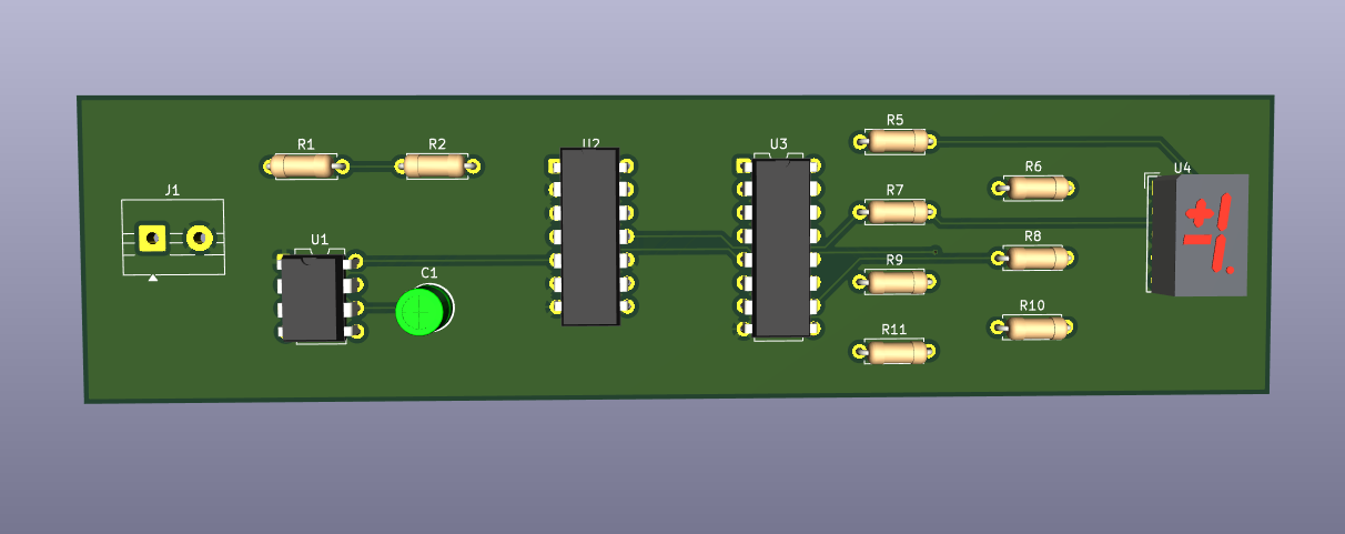
This started with a pretty simple goal: make a 7-segment display count from 0 to 9 without using a microcontroller. I first wired the circuit on a breadboard, checked that the counter worked, and then tried to fit the same idea onto a board I could design myself.
The interesting part wasn't the counting. It was figuring out how the clock, counter, decoder, resistors, and display all needed to connect, then translating that into an actual PCB layout.
NE555 timer (clock)
        |
        v
74LS90 decade counter (0–9)
        |
        v
4511 BCD-to-7-segment decoder
        |
        v
7-segment display (HDSP-7503)
The NE555 provides the pulses. The 74LS90 counts them through the ten decimal states. The 4511 translates the BCD output into signals for the display. Seven 220 Ω resistors limit current through the display segments.
The KiCad schematic also includes a 1 kΩ resistor, a 10 kΩ resistor, a polarized capacitor, and a two-pin power connection. I used an external 5 V breadboard power module during prototyping rather than designing a regulator onto this board.
| PCB layout | Schematic |
|---|---|
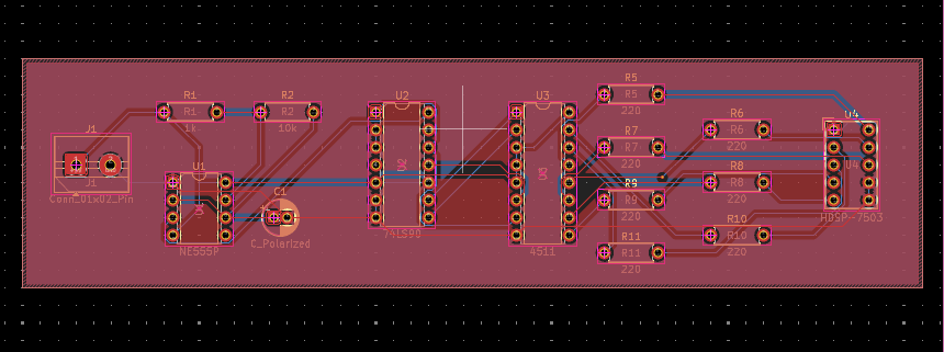 | 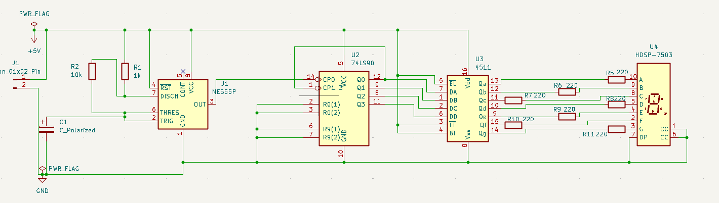 |
After getting the breadboard circuit running, I redrew it in KiCad, assigned the through-hole footprints, and routed the board. This was a useful introduction to how much more deliberate you have to be once your wires become copper traces.
The schematic records KiCad 10.0 as its generating version. Use KiCad 10.0 to review the files in their original tool version.
The PNGs in Images/ are previews; edit the KiCad source files to change the design. The repository contains no exported Gerber or NC drill files. If preparing a board order, rerun ERC/DRC and generate fabrication outputs from the reviewed PCB first.
I'm leaving the project as it is for now. It was a small circuit, but it was an important step in going from connecting components to designing the board those components sit on.
Built by Adhyayan Tiwari · MIT License
| Qty | Value | Footprint | References |
|---|---|---|---|
| 7 | 220 | Resistor_THT:R_Axial_DIN0207_L6.3mm_D2.5mm_P7.62mm_Horizontal | R5, R6, R7, R8, R9, R10, R11 |
| 1 | 10k | Resistor_THT:R_Axial_DIN0207_L6.3mm_D2.5mm_P7.62mm_Horizontal | R2 |
| 1 | 1k | Resistor_THT:R_Axial_DIN0207_L6.3mm_D2.5mm_P7.62mm_Horizontal | R1 |
| 1 | 4511 | Package_DIP:DIP-16_W7.62mm | U3 |
| 1 | 74LS90 | Package_DIP:DIP-14_W7.62mm | U2 |
| 1 | C_Polarized | Capacitor_THT:CP_Radial_D5.0mm_P2.00mm | C1 |
| 1 | Conn_01x02_Pin | TerminalBlock:TerminalBlock_MaiXu_MX126-5.0-02P_1x02_P5.00mm | J1 |
| 1 | HDSP-7503 | Display_7Segment:HDSP-7507 | U4 |
| 1 | NE555P | Package_DIP:DIP-8_W7.62mm | U1 |


Roshan-khatri78/Electronics-Projects-KiCad-
A collection of my KiCad projects and PCB designs. These projects reflect my learning journey in electronics and PCB design.


baldengineer/bit-preserve
Project for capturing vintage, classic, aka old computer schematics in KiCad.

The-Invent0r/8-bit-Computer-PCB
These are the KiCAD files for my 8-Bit Computer.
It measures 129.5 × 33 mm and has 2 copper layers, 1.6 mm thick.
15 parts, built around the HDSP-7503 and NE555P. The full list of its parts is on this page, with links to each part's symbol and footprint where PCBKit's library has them.
From the adhyayan15/BCD_Decade_Counter repository on GitHub, at the commit this page was made from: the board is KiCad/BCD Decade Counter.kicad_pcb and its schematic KiCad/BCD Decade Counter.kicad_sch. PCBKit opens the board in the browser, with nothing to install.
Its repository publishes it under the MIT licence: you may reuse it on that licence's terms (keep the author's notice, and for a copyleft licence share your changes alike).