2 layers48.3 × 99.1 mm
Modulation source
JordanAceto/modulation_source
Eurorack compatible pcb with sine/square VCLFO, white and pink noise, and sample & hold
95 parts6

 JordanAceto/quad_ADSR_board5
PCB for a quad eurorack ADSR
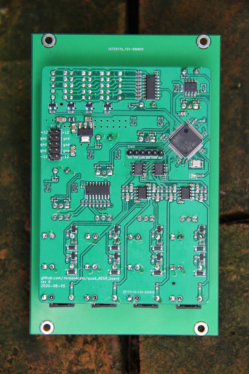
Quad adsr is an open-source printed circuit board by JordanAceto, from the JordanAceto/quad_ADSR_board repository on GitHub. It is a 4-layer board of 71.1 × 99.1 mm with 197 parts on 160 nets, routed with 1,195 tracks and 164 vias.
It is built around the MCP4822-E/P, TL072 and HDSP-7503, with the 74HC595, 24LC32A/P and AMS1117-3.3 among its other parts. Its parts include 86 resistors, 53 capacitors, 14 connectors, 13 ICs and 13 diodes. It belongs with the STM32 boards of this library.


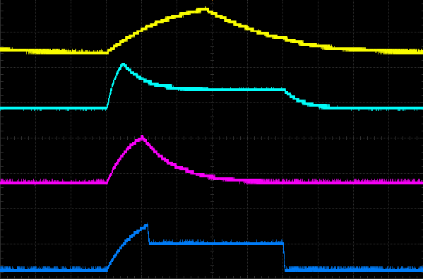
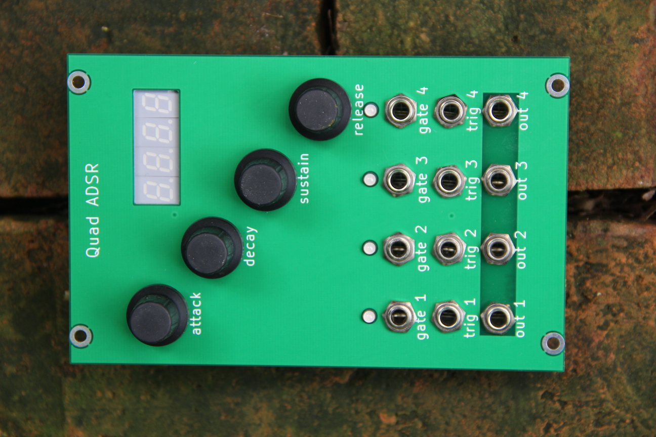
One ADSR at a time is set as the "active" ADSR, which will be controlled by the encoders.
To select an ADSR as "active", the encoder push-button above a given ADSR is pressed.
The four-digit seven-segment display shows the parameter of the encoder that was most recently turned. For instance, if you just turned the decay time to 500 milliseconds, the display will show 0.500. If you then adjust the sustain level to 68%, the display will now show 68. Time based parameters are shown in units of seconds, and sustain parameters are shown as 0% to 100%.
Additionally, the ADSRs can all be forced to lock to a "master" ADSR, so that that their attack, decay, sustain, and release parameters are all set the same. The four ADSRs can still be triggered independently in this mode, which makes this useful for polyphonic patches. This saves you from manually setting identical paramters four times. Lock-to-master mode is selected by performing a long push-switch press of the encoder above the desired ADSR. For instance, to force all the ADSRs to lock to the ADSR 3 settings, depress and hold the sustain encoder push-button for a few seconds. To leave lock-to-master mode, do a short click of any of the encoder push-buttons to select a new active ADSR.
A bank of four bi-color LEDs shows the active ADSR, and whether it is in independent, or lock-to-master mode.
release_ADSRs_from_master_mode or something that accomplishes this, and call that function when leaving lock-to-master modemain.list output file occasionally-Os or -O2 and make sure that nothing breaks. There might be some volatile issues, or necessary code that gets optimized away, be careful and thorough!| Qty | Value | Footprint | References |
|---|---|---|---|
| 24 | 100nF | Capacitor_SMD:C_0402_1005Metric | C3, C12, C16, C17, C18, C19, C20, C21, C22, C23, C24, C25, C26, C27, C28, C29 +8 |
| 18 | 10k | Resistor_SMD:R_0402_1005Metric | R1, R2, R3, R4, R7, R8, R10, R13, R14, R15, R16, R19, R20, R21, R22, R82 +2 |
| 16 | 390 | Resistor_SMD:R_0603_1608Metric | R26, R27, R28, R29, R30, R31, R32, R33, R37, R38, R39, R40, R41, R42, R43, R44 |
| 12 | 10k | Resistor_SMD:R_0603_1608Metric | R25, R34, R35, R36, R50, R52, R54, R56, R58, R60, R62, R64 |
| 12 | MMBT3904 | Package_TO_SOT_SMD:SOT-23 | Q1, Q2, Q3, Q4, Q5, Q6, Q7, Q8, Q9, Q10, Q11, Q12 |
| 8 | 100k | Resistor_SMD:R_0603_1608Metric | R49, R51, R53, R55, R57, R59, R61, R63 |
| 8 | 10nF | Capacitor_SMD:C_0402_1005Metric | C1, C2, C4, C5, C7, C8, C10, C11 |
| 8 | 1N4148W | Diode_SMD:D_SOD-123 | D6, D7, D8, D9, D10, D11, D12, D13 |
| 8 | 2n2 | Capacitor_SMD:C_0805_2012Metric_Pad1.15x1.40mm_HandSolder | C37, C38, C39, C40, C41, C42, C43, C44 |
| 5 | 100 | Resistor_SMD:R_0402_1005Metric | R6, R12, R18, R24, R84 |
| 4 | 100nF | Capacitor_SMD:C_0603_1608Metric | C33, C34, C35, C36 |
| 4 | 1k | Resistor_SMD:R_0603_1608Metric | R45, R46, R47, R48 |
| 4 | 200k | Resistor_SMD:R_0603_1608Metric | R67, R68, R75, R76 |
| 4 | 33k | Resistor_SMD:R_0603_1608Metric | R69, R70, R77, R78 |
| 4 | 4k7 | Resistor_SMD:R_0402_1005Metric | R5, R11, R17, R23 |
| 4 | 50k | Resistor_SMD:R_0603_1608Metric | R65, R66, R73, R74 |
| 4 | 68k | Resistor_SMD:R_0603_1608Metric | R71, R72, R79, R80 |
| 4 | HDSP-7503 | Display_7Segment:HDSP-A151 | U1, U3, U4, U5 |
| 4 | LED_Dual_ACA | LED_THT:LED_D3.0mm-3 | D1, D2, D3, D4 |
| 4 | PJ301M-12 | Eurocad:PJ301M-12 | J1, J2, J3, J4 |
| 4 | Rotary_Encoder_Switch | Rotary_Encoder:RotaryEncoder_Alps_EC11E-Switch_Vertical_H20mm | ENC1, ENC2, ENC3, ENC4 |
| 3 | 10uF | Capacitor_SMD:C_1206_3216Metric | C13, C51, C52 |
| 2 | 10uF | Capacitor_SMD:C_0805_2012Metric | C14, C15 |
| 2 | 12pF | Capacitor_SMD:C_0402_1005Metric | C47, C48 |
| 2 | 2.2uF | Capacitor_SMD:C_0603_1608Metric | C45, C46 |
| 2 | 4k7 | Resistor_SMD:R_0603_1608Metric | R85, R86 |
| 2 | 74HC595 | Package_SO:SOIC-16_3.9x9.9mm_P1.27mm | U2, U6 |
| 2 | MCP4822 | Package_SO:SOIC-8_3.9x4.9mm_P1.27mm | U9, U10 |
| 2 | TL072 | Package_SO:SOIC-8_3.9x4.9mm_P1.27mm | U8, U11 |
| 1 | 16MHz | Crystal:Crystal_SMD_3225-4Pin_3.2x2.5mm | HSE1 |
| 1 | 24LC32 | Package_SO:SOIC-8_3.9x4.9mm_P1.27mm | U13 |
| 1 | 2k2 | Resistor_SMD:R_0603_1608Metric | R81 |
| 1 | AMS1117-3.3 | Package_TO_SOT_SMD:SOT-223-3_TabPin2 | U7 |
| 1 | Ferrite_Bead_Small | Inductor_SMD:L_0805_2012Metric | FB1 |
| 1 | LED | LED_SMD:LED_0603_1608Metric | D5 |
| 1 | STM32F405RGTx | Package_QFP:LQFP-64_10x10mm_P0.5mm | U12 |
| 1 | SWD_header | Connector_PinHeader_2.54mm:PinHeader_1x06_P2.54mm_Vertical | J14 |
| 1 | gate_1_i n | Eurocad:PJ301M-12 | J6 |
| 1 | gate_2_in | Eurocad:PJ301M-12 | J8 |
| 1 | gate_3_in | Eurocad:PJ301M-12 | J10 |
| 1 | gate_4_in | Eurocad:PJ301M-12 | J12 |
| 1 | power_in | Connector_PinHeader_2.54mm:PinHeader_2x05_P2.54mm_Vertical | J5 |
| 1 | trigger_1_in | Eurocad:PJ301M-12 | J7 |
| 1 | trigger_2_in | Eurocad:PJ301M-12 | J9 |
| 1 | trigger_3_in | Eurocad:PJ301M-12 | J11 |
| 1 | trigger_4_in | Eurocad:PJ301M-12 | J13 |
JordanAceto/modulation_source
Eurorack compatible pcb with sine/square VCLFO, white and pink noise, and sample & hold

punkfab/pcb-corpus
235 real KiCad boards from open-source hardware repositories, prepared as a placement and routing benchmark

fossasia/pslab-hardware
PSLab Hardware Design and Schematics https://pslab.io

JordanAceto/SSM2164-SVF
State variable filter with audio and super low frequency modes

Thorinair/Avalon-Harmonics
A collection of Avalon Harmonics branded synthesizer modules.

cpldcpu/TouchSynth
Analog Monophonic Synthesizer with a touch keyboard. Controller by CH32V00x

JordanAceto/micro_ox
Monosynth with analog signal path and digital controls. SSI2130 VCOs and SSI2140 VCF.

MadsRudolph/vinyl-adc
Discrete 3rd-order delta-sigma stereo audio ADC, built from op-amps and logic gates: a four-layer Raspberry Pi HAT made by PCBWay, with KiCad files, SPICE simulations and measurements
It measures 71.1 × 99.1 mm and has 4 copper layers, 1.6 mm thick.
197 parts, built around the MCP4822-E/P, TL072, HDSP-7503 and 74HC595. The full list of its parts is on this page, with links to each part's symbol and footprint where PCBKit's library has them.
From the JordanAceto/quad_ADSR_board repository on GitHub, at the commit this page was made from: the board is hardware/main_pcb/kicad_docs/quad_adsr.kicad_pcb. PCBKit opens the board in the browser, with nothing to install.
Its repository states no licence, so its author keeps all rights: ask JordanAceto before reusing the design.