
2 layers101.6 × 53.3 mm

 adhidass/LED-Light-Sensor-PCB
Powered by 3.3 V through a 3-pin header (3.3 V, Vout, GND).
LED Light Sensor is an open-source printed circuit board by adhidass, from the adhidass/LED-Light-Sensor-PCB repository on GitHub. It is a 2-layer board of 34.5 × 41 mm with 12 parts on 7 nets, routed with 49 tracks and 2 vias.
It is built around the LMC6482IN. Its parts include 3 resistors, 2 capacitors, 1 IC, 1 diode and 1 connector. It belongs with the sensors and measurement boards of this library.
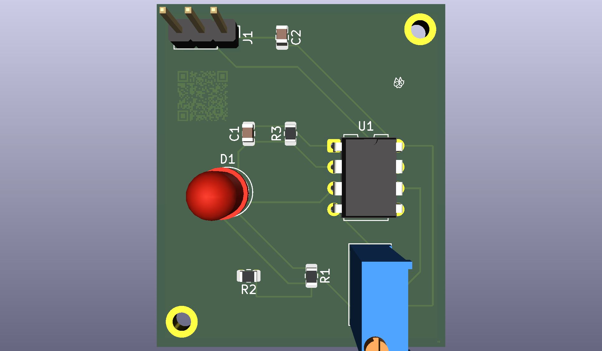
Powered by 3.3 V through a 3-pin header (3.3 V, Vout, GND).
Designed in KiCad, DRC clean. Not yet fabricated or tested.
Hardware/: KiCad project filesDocs/: schematic PDF and board imageLED Light Sensor.zip: Gerber and drill files for manufacturingA step by step tutorial by @inkedbhav on tiktok. Assisted by Claude AI (Sonnet 5.5)
| Qty | Value | Footprint | References |
|---|---|---|---|
| 2 | 10k | Resistor_SMD:R_0805_2012Metric | R1, R2 |
| 2 | MountingHole_2.2mm_M2_DIN965_Pad | MountingHole:MountingHole_2.2mm_M2_DIN965_Pad | , |
| 1 | 100nF | Capacitor_SMD:C_0805_2012Metric | C1 |
| 1 | 1nF | Capacitor_SMD:C_0805_2012Metric | C2 |
| 1 | 5.1M | Resistor_SMD:R_0805_2012Metric | R3 |
| 1 | Conn_01x03 | Connector_PinHeader_2.54mm:PinHeader_1x03_P2.54mm_Vertical | J1 |
| 1 | LED | LED_THT:LED_D5.0mm | D1 |
| 1 | LMC6482 | Package_DIP:DIP-8_W7.62mm | U1 |
| 1 | LOGO | Signatures:signature | |
| 1 | R_Potentiometer | Potentiometer_THT:Potentiometer_Bourns_3296W_Vertical | RV1 |
It measures 34.5 × 41 mm and has 2 copper layers, 1.6 mm thick.
12 parts, built around the LMC6482IN. The full list of its parts is on this page, with links to each part's symbol and footprint where PCBKit's library has them.
From the adhidass/LED-Light-Sensor-PCB repository on GitHub, at the commit this page was made from: the board is Hardware/LED Light Sensor.kicad_pcb and its schematic Hardware/LED Light Sensor.kicad_sch. PCBKit opens the board in the browser, with nothing to install.
Its repository states no licence, so its author keeps all rights: ask adhidass before reusing the design.

neurotech-berkeley/eog-eye-tracking
Exploration of EOG (electrooculogram) signals as a potential human computer interface

ElektroNeo/Adjustable-Wireless-Neuro-Stimulator-System
🧠 0-5.5mA adjustable wireless neurostimulator system made with PIC16F1713 and App Inventor.


