2 layers100 × 50 mm
Power Supply
adsehgal/Bench_Power_Supply
A design for a custom bench top power supply for prototyping.
106 parts2

 glenoverby/gpsdo35
Improved GPS Disciplined Oscillator
Gpsdo3 is an open-source printed circuit board by glenoverby, from the glenoverby/gpsdo3 repository on GitHub. It is a 2-layer board of 73.7 × 48.3 mm with 55 parts on 62 nets, routed with 293 tracks and 28 vias.
It is built around the 74LVC125AD, MIC5205-5.0YM5 and LMC6482IN, with the MIC5205-3.3YM5 among its other parts. Its parts include 11 capacitors, 11 resistors, 7 ICs, 7 connectors and 4 diodes. It belongs with the radio and wireless boards of this library.


Improved GPS Disciplined Oscillator
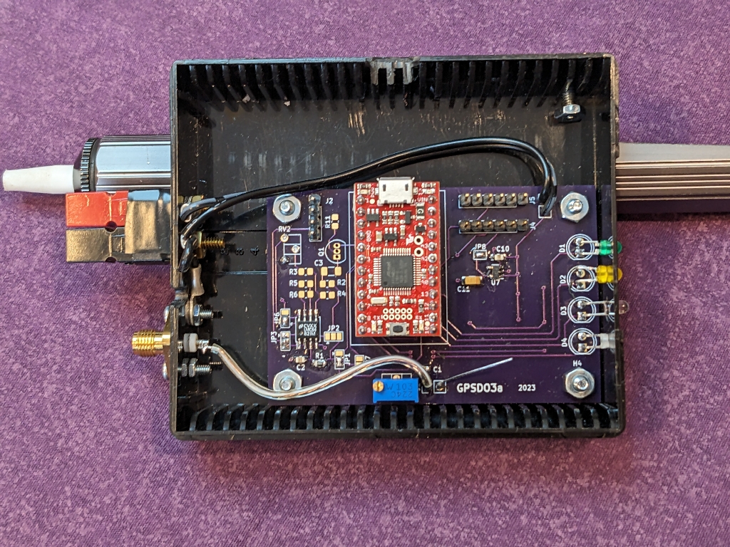
This is a GPS Disciplined Oscillator for synchronizing a 10MHz osillator with the timing signal from GPS.
This project include a printed circuit board (designed in KiCad) and software (using Arduino). It runs on a SparkFun SAMD21 Mini Breakout.
A full description of the project is in the 'doc' directory.
| Qty | Value | Footprint | References |
|---|---|---|---|
| 5 | R_US | Resistor_SMD:R_0805_2012Metric_Pad1.20x1.40mm_HandSolder | R7, R8, R9, R10, R11 |
| 4 | 100K | Resistor_SMD:R_0805_2012Metric_Pad1.20x1.40mm_HandSolder | R1, R2, R3, R4 |
| 4 | 1uF | Capacitor_SMD:C_0805_2012Metric_Pad1.18x1.45mm_HandSolder | C2, C4, C5, C10 |
| 4 | LED | LED_THT:LED_D5.0mm | D1, D2, D3, D4 |
| 4 | MountingHole | MountingHole:MountingHole_3.2mm_M3 | H1, H2, H3, H4 |
| 3 | 2.2uF | Capacitor_SMD:C_1206_3216Metric_Pad1.33x1.80mm_HandSolder | C8, C9, C11 |
| 2 | 10K | Resistor_SMD:R_0805_2012Metric_Pad1.20x1.40mm_HandSolder | R5, R6 |
| 2 | 470pF | Capacitor_SMD:C_0805_2012Metric_Pad1.18x1.45mm_HandSolder | C6, C7 |
| 2 | MIC5205-5.0YM5 | Package_TO_SOT_SMD:SOT-23-5 | U6, U7 |
| 1 | 10K | Potentiometer_THT:Potentiometer_ACP_CA6-H2,5_Horizontal | RV2 |
| 1 | 1uF | Capacitor_SMD:C_1206_3216Metric_Pad1.33x1.80mm_HandSolder | C3 |
| 1 | 2N3904 | Package_TO_SOT_THT:TO-92_Inline | Q1 |
| 1 | 3.3V Jumper | Jumper:SolderJumper-2_P1.3mm_Open_Pad1.0x1.5mm | JP8 |
| 1 | 5V #1 Jumper | Jumper:SolderJumper-2_P1.3mm_Open_Pad1.0x1.5mm | JP4 |
| 1 | 5V #2 Jumper | Jumper:SolderJumper-2_P1.3mm_Open_Pad1.0x1.5mm | JP5 |
| 1 | 74LVC125 | Package_SO:SOIC-14_3.9x8.7mm_P1.27mm | U2 |
| 1 | C | Capacitor_SMD:C_0805_2012Metric_Pad1.18x1.45mm_HandSolder | C1 |
| 1 | CPU PWM - DAC | Jumper:SolderJumper-3_P1.3mm_Open_Pad1.0x1.5mm | JP1 |
| 1 | Conn_01x02_Male | Connector_PinHeader_2.54mm:PinHeader_1x02_P2.54mm_Vertical | J6 |
| 1 | Conn_01x02_Male | Capacitor_SMD:C_0805_2012Metric_Pad1.18x1.45mm_HandSolder | J7 |
| 1 | Conn_Coaxial | Connector_PinHeader_2.54mm:PinHeader_1x02_P2.54mm_Vertical | J1 |
| 1 | Gate2 Input | Jumper:SolderJumper-3_P1.3mm_Open_Pad1.0x1.5mm | JP2 |
| 1 | LMC6482 | Package_SO:SOIC-8_5.23x5.23mm_P1.27mm | U1 |
| 1 | MCP4725xxx-xCH | Package_TO_SOT_SMD:SOT-23-6 | U4 |
| 1 | MIC5205-3.3YM5 | Package_TO_SOT_SMD:SOT-23-5 | U5 |
| 1 | OSC Vcontrol | Jumper:SolderJumper-3_P1.3mm_Open_Pad1.0x1.5mm | JP3 |
| 1 | Power | Connector_PinHeader_2.54mm:PinHeader_1x02_P2.54mm_Vertical | J3 |
| 1 | R_Potentiometer_US | Potentiometer_THT:Potentiometer_ACP_CA6-H2,5_Horizontal | RV1 |
| 1 | SFE_SAMD21_Mini | Glen_Arduino:SFE SAMD21 Mini | U3 |
| 1 | SolderJumper_2_Open | Jumper:SolderJumper-2_P1.3mm_Open_Pad1.0x1.5mm | JP7 |
| 1 | To Computer | Connector_PinHeader_2.54mm:PinHeader_1x06_P2.54mm_Vertical | J5 |
| 1 | To GPS | Connector_PinHeader_2.54mm:PinHeader_1x06_P2.54mm_Vertical | J4 |
| 1 | To OSC | Connector_PinHeader_2.54mm:PinHeader_1x04_P2.54mm_Vertical | J2 |
| 1 | ~ | Jumper:SolderJumper-3_P1.3mm_Open_Pad1.0x1.5mm | JP6 |
It measures 73.7 × 48.3 mm and has 2 copper layers, 1.6 mm thick.
55 parts, built around the 74LVC125AD, MIC5205-5.0YM5, LMC6482IN and MIC5205-3.3YM5. The full list of its parts is on this page, with links to each part's symbol and footprint where PCBKit's library has them.
From the glenoverby/gpsdo3 repository on GitHub, at the commit this page was made from: the board is board/GPSDO3.kicad_pcb and its schematic board/GPSDO3.kicad_sch. PCBKit opens the board in the browser, with nothing to install.
Its repository states no licence, so its author keeps all rights: ask glenoverby before reusing the design.
adsehgal/Bench_Power_Supply
A design for a custom bench top power supply for prototyping.


skumlos/atmega328pb-nano
An Arduino Mini Pro clone using a Atmega328PB instead to have 2 I2C busses


git4dcc/RTB_E13
Universal charlieplexing WS28xx emulator with variable LED voltage.

git4dcc/RTB_E15
Universal charlieplexing WS28xx emulator with fixed LED voltage.