

2 layers48.4 × 21.6 mm
E15
git4dcc/RTB_E15
Universal charlieplexing WS28xx emulator with fixed LED voltage.
26 partsApache-2.0
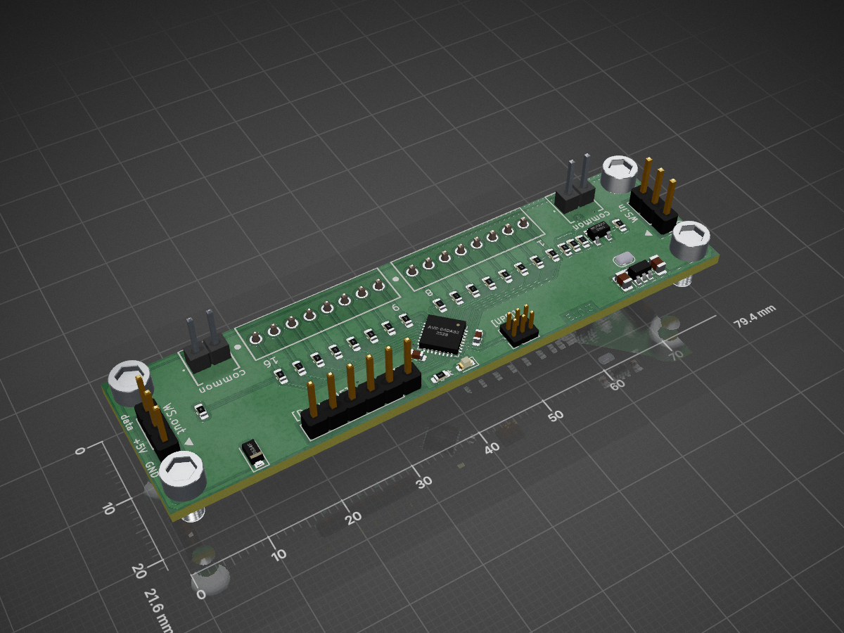
Universal 16 channel WS28xx emulator.
E10 is an open-source printed circuit board by git4dcc, from the git4dcc/RTB_E10 repository on GitHub, published under the Apache-2.0 licence. It is a 2-layer board of 79.4 × 21.6 mm with 45 parts on 50 nets, routed with 254 tracks and 20 vias.
It is built around the AVR64DA32-E/PT, MCP6001OB and MIC5205-5.0YM5, with the SS34F among its other parts. Its parts include 22 resistors, 8 connectors, 4 capacitors, 3 ICs and 2 diodes.


This E10 module implements a 16 channel WS2811 emulator with compatible bus timing. The E10 may be cascaded with regular WS28xx chips. The number of LEDs is auto detected/configured (0-16). Optionally, the common LED voltage can be controlled over the bus as well.
<img src=supplemental/images/E10_main.jpg>
The decoder has the following features,
My current PCB layout uses SMD footprints with 0.5mm pitch and 0603 parts. Reflow soldering is my recommendation, but with some experience handsoldering is also possible.
The hardware allows either push or pull operation. Currently only the pull operation is implemented in the firmware. Should a usecase for push-operation arise, the firmware could be adapted.
<img src=supplemental/images/E10_top_connect.jpg>
:yellow_circle: Requires my Kicad project library RTB_SamacSys in the same directory tree.
Filename structure: { pcb }{ code }{ version }.hex
Example: E10F0001.hex
| Description | |
|---|---|
| pcb | Name of matching hardware (E10) |
| code | Type of code contained (R=rom, B=bootloader, F=flash, U=bld update, P=UPDI factory code) |
| version | Release version (####) |
The fuse settings as well as the P-code (E10Pxxxx.hex) has to be installed by using UPDI.
<img src=supplemental/images/E10_updi.jpg>
| Fuse Setting | P-Code Install |
|---|---|
| <img src=supplemental/images/E10_updi_fuses.jpg width=500> | <img src=supplemental/images/E10_updi_memory.jpg width=500> |
Subsequent code updates can be done via the built-in serial debug interface.
connect the serial cable (1Mb, 8N1, RTS/CTS)
press 'break' within the VT100 terminal to bump the module to console prompt
upload the firmware file (E10Fxxxx.hex)
for more details, refer to the 'User Guide'
<img src=supplemental/images/E10_debugIF.jpg>
The LED common voltage must be sent as the first byte (virtual LED) over the bus followed by the intensity values for the individual LEDs.
Byte order:     {voltage} {led_0} ... {led_n}      //'n' being the number of configured LEDs
Led Voltage: 5V * {voltage} / 255<img src=supplemental/images/E10_samples.jpg width=260> <img src=supplemental/images/E10_usecase.jpg width=265>
This project is intended for hobby use only and is distributed in accordance with the Apache License 2.0 agreement.
| Qty | Value | Footprint | References |
|---|---|---|---|
| 16 | 220 | Resistor_SMD:R_0603_1608Metric | R2, R3, R4, R5, R6, R7, R8, R9, R10, R11, R12, R13, R14, R15, R16, R17 |
| 4 | MountingHole | MountingHole:MountingHole_3.2mm_M3_DIN965 | H1, H2, H3, H4 |
| 2 | 100n | Capacitor_SMD:C_0603_1608Metric | C2, C3 |
| 2 | 160 | Resistor_SMD:R_0603_1608Metric | R18, R19 |
| 2 | 4.7u/10V | Capacitor_SMD:C_0805_2012Metric | C1, C4 |
| 2 | 47k | Resistor_SMD:R_0603_1608Metric | R24, R25 |
| 1 | 22 | Resistor_SMD:R_0603_1608Metric | R23 |
| 1 | 4.7k | Resistor_SMD:R_0603_1608Metric | R20 |
| 1 | AVR-64da32 | Package_DFN_QFN:QFN-32-1EP_5x5mm_P0.5mm_EP3.1x3.1mm | U1 |
| 1 | Debug | Connector_PinHeader_2.54mm:PinHeader_1x06_P2.54mm_Vertical | J5 |
| 1 | HBT(green) | LED_SMD:LED_0603_1608Metric | D2 |
| 1 | LED 0-7 | RTB_parts:1725711 | J7 |
| 1 | LED 8-15 | RTB_parts:1725711 | J1 |
| 1 | LED Common | RTB_parts:1725656 | J8 |
| 1 | LED common | RTB_parts:1725656 | J6 |
| 1 | MCP6001 | Package_TO_SOT_SMD:SOT-23-5 | U3 |
| 1 | MIC5205-5.0YM5 | Package_TO_SOT_SMD:SOT-23-5 | U2 |
| 1 | SS34F | Diode_SMD:D_SOD-123F | D1 |
| 1 | SolderJumper_2_Open | Jumper:SolderJumper-2_P1.3mm_Open_RoundedPad1.0x1.5mm | JP1 |
| 1 | SolderJumper_3_Open | Jumper:SolderJumper-3_P1.3mm_Open_RoundedPad1.0x1.5mm | JP2 |
| 1 | UPDI | Connector_PinHeader_1.27mm:PinHeader_2x03_P1.27mm_Vertical | J4 |
| 1 | WS-bus input | Connector_PinHeader_2.54mm:PinHeader_1x03_P2.54mm_Vertical | J3 |
| 1 | WS-bus output | Connector_PinHeader_2.54mm:PinHeader_1x03_P2.54mm_Vertical | J2 |
It measures 79.4 × 21.6 mm and has 2 copper layers, 1.6 mm thick.
45 parts, built around the AVR64DA32-E/PT, MCP6001OB, MIC5205-5.0YM5 and SS34F. The full list of its parts is on this page, with links to each part's symbol and footprint where PCBKit's library has them.
From the git4dcc/RTB_E10 repository on GitHub, at the commit this page was made from: the board is E10.kicad_pcb. PCBKit opens the board in the browser, with nothing to install.
Its repository publishes it under the Apache-2.0 licence: you may reuse it on that licence's terms (keep the author's notice, and for a copyleft licence share your changes alike).
git4dcc/RTB_E15
Universal charlieplexing WS28xx emulator with fixed LED voltage.

cehbz/aqm-fan-controller
KiCad PCB design for a PWM fan controller (ESP32-C3, TPS562201 buck converter)


ymhtwe/SGW01
ESP-IDF based IoT gateway for solar pump monitoring and control using SIM7600 4G modem and Modbus RTU.


