2 layers42 × 20 mm

 neurotech-berkeley/eog-eye-tracking7
Exploration of EOG (electrooculogram) signals as a potential human computer interface
Eog pcb kicad is an open-source printed circuit board by neurotech-berkeley, from the neurotech-berkeley/eog-eye-tracking repository on GitHub, published under the MIT licence. It is a 4-layer board of 60 × 41 mm with 82 parts on 56 nets, routed with 551 tracks and 81 vias.
It is built around the MAX764ESA+, LMC6482IN and AD5160BRJZ5-RL7, with the AD8402ARZ1 and MBRS330T3G among its other parts. Its parts include 34 capacitors, 19 resistors, 13 ICs, 6 diodes and 4 connectors.


Exploration of EOG (electrooculogram) signals as a potential human computer interface.
This project was one of Neurotech@Berkeley's Devices Division projects in Spring 2022. At Devices, we build hardware for the brain - to measure and analyze electrical signals generated by our bodies to see if we can come up with new ways to interact with computers. You can learn more about our organization as a whole at neurotech.berkeley.edu.
Inspired by the potential that the gaze-tracking systems, we set out to explore a technique with substantially lower computational cost than computer vision: electrooculography (EOG). Unlike computer vision that relies on cameras, EOG relies on intrintic electric signals generated in our eye.
In this project, we prototyped, designed, fabricated, and tested analog front end (AFE) circuit to control a dinosaur chrome game.
In this demo, we connected our custom-designed PCB to a laptop through an Arduino. The dinosaur is controlled by blinks alone, hands and keyboard-free.
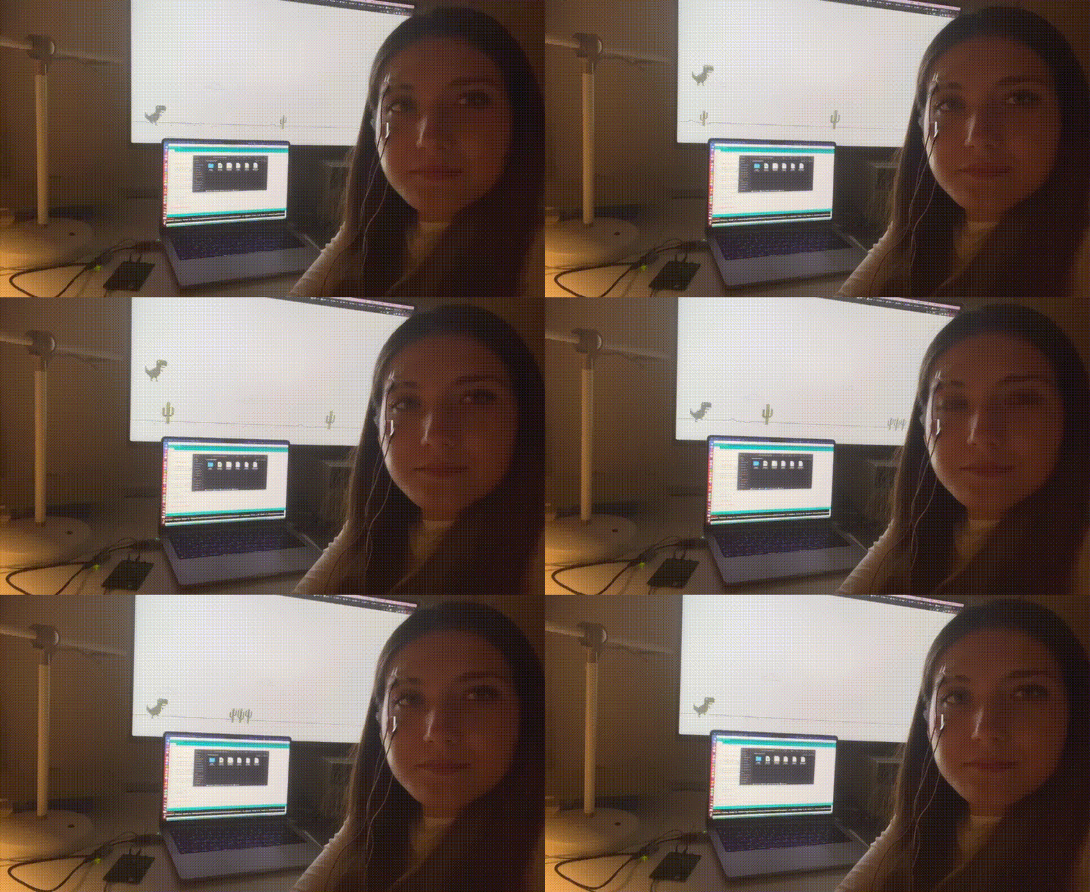
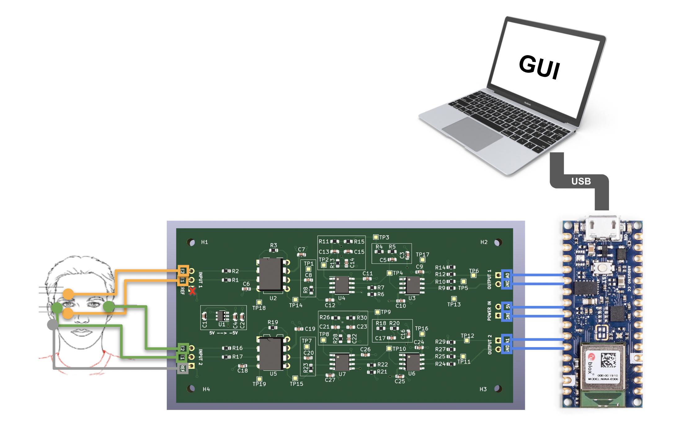 In this initial setup, we use three electrodes (2 attaching above and below an eye, and 1 fore reference behind an ear). These electrodes then attach to our PCB that amplify and filter from noise the difference between the two electrodes. The PCB is able to output a voltage acceptable by most 5V-operated microcontrollers (like Arduino, for example). The output of one channel is just an analog voltage that can be read by an onboard ADC on a microcontroller, which then can get transmitted to a laptop through a USB port for real-time analysis.
Here are some potential improvements and ideas that we want to incorporate in future iterations of the design:
Currently, the PCB is communicating to the laptop through USB cable, but it would be cool to make it wireless! Open to exploring bluetooth chips other than Arduino. This would potentially mean exploring power consumption of the device and including a charging circuit.
Currently, the AFE of our PCB is configured specifically for EOG signals, but it would be cool to make it adjustable to other types of signals by incorporating tunable resistors/capacitors in filters.
Currently, we tell the difference between looking up and down by using basic thresholding :P
Moving away from playing games, we want to explore incorporating eye tracking into an every-day workflow!
| Qty | Value | Footprint | References |
|---|---|---|---|
| 14 | 0.1uF | Capacitor_SMD:C_0603_1608Metric | C2, C6, C7, C9, C10, C11, C12, C18, C19, C24, C25, C26, C27, C33 |
| 12 | 10uF | Capacitor_SMD:C_0603_1608Metric | C3, C5, C8, C16, C17, C20, C81, C82, C83, C201, C202, C203 |
| 4 | 1k | Resistor_SMD:R_0603_1608Metric | R12, R14, R27, R29 |
| 4 | 1uF | Capacitor_SMD:C_0603_1608Metric | C13, C15, C21, C23 |
| 4 | 220k | Resistor_SMD:R_0603_1608Metric | R1, R2, R16, R17 |
| 4 | 2k7 | Resistor_SMD:R_0603_1608Metric | R11, R15, R26, R30 |
| 4 | D5V0 | Resistor_SMD:R_0603_1608Metric | D2, D3, D4, D5 |
| 4 | LMC6482 | Package_SO:SOIC-8_3.9x4.9mm_P1.27mm | U3, U4, U6, U7 |
| 4 | MountingHole | MountingHole:MountingHole_2.2mm_M2 | H1, H2, H3, H4 |
| 2 | 1k3 | Resistor_SMD:R_0603_1608Metric | R13, R28 |
| 2 | 2k2 | Resistor_SMD:R_0603_1608Metric | R3, R19 |
| 2 | 2uF | Capacitor_SMD:C_0603_1608Metric | C14, C22 |
| 2 | AD5160BRJZ5-RL7 | Package_TO_SOT_SMD:SOT-23-8 | U9, U12 |
| 2 | AD620 | Package_SO:SOIC-8_3.9x4.9mm_P1.27mm | U2, U5 |
| 2 | AD8402ARZ1 | Package_SO:SOIC-14_3.9x8.7mm_P1.27mm | U1, U11 |
| 2 | Conn_01x03 | Connector_PinHeader_2.54mm:PinHeader_1x03_P2.54mm_Vertical | J1, J4 |
| 2 | MAX5401EKAT | Package_TO_SOT_SMD:SOT-23-8 | U10, U13 |
| 1 | 100uF | 20TQC100MYF:CAP_20TQC100MYF | C1 |
| 1 | 150 | Resistor_SMD:R_0603_1608Metric | R4 |
| 1 | 150R | Resistor_SMD:R_0603_1608Metric | R24 |
| 1 | 400 | Resistor_SMD:R_0603_1608Metric | R5 |
| 1 | 47uH | NRS6028T470M:IND_NRS6028T470M | L1 |
| 1 | 68uF | 20TQC100MYF:CAP_20TQC100MYF | C4 |
| 1 | Conn_01x04 | Connector_PinHeader_2.54mm:PinHeader_1x04_P2.54mm_Vertical | J3 |
| 1 | Conn_01x08 | Connector_PinHeader_2.54mm:PinHeader_1x08_P2.54mm_Vertical | J2 |
| 1 | LED | LED_SMD:LED_0603_1608Metric | LED1 |
| 1 | LOGO | LOGO | G*** |
| 1 | MAX764ESA+ | Package_SO:SOIC-8_3.9x4.9mm_P1.27mm | U8 |
| 1 | MBRS330T3G | MBRS330T3G:DIOM7959X261N | D1 |
It measures 60 × 41 mm and has 4 copper layers, 1.6 mm thick.
82 parts, built around the MAX764ESA+, LMC6482IN, AD5160BRJZ5-RL7 and AD8402ARZ1. The full list of its parts is on this page, with links to each part's symbol and footprint where PCBKit's library has them.
From the neurotech-berkeley/eog-eye-tracking repository on GitHub, at the commit this page was made from: the board is eog-pcb-kicad/eog-pcb-kicad.kicad_pcb and its schematic eog-pcb-kicad/channel_1.kicad_sch. PCBKit opens the board in the browser, with nothing to install.
Its repository publishes it under the MIT licence: you may reuse it on that licence's terms (keep the author's notice, and for a copyleft licence share your changes alike).


alexismartin46/Cours_Electronique_de_Puissance_FISE2
L'objectif de cette maquette est de pouvoir réaliser des mesures autour d'un convertisseur Buck afin d'expliquer aux étudiants le fonctionnement et les caractéristiques d'un tel convertisseur.


ElektroNeo/Adjustable-Wireless-Neuro-Stimulator-System
🧠 0-5.5mA adjustable wireless neurostimulator system made with PIC16F1713 and App Inventor.


