
4 layers86 × 56 mm

 AccelRanger/macropad
Custom macropad with custom PCB and firmware
Macropad is an open-source printed circuit board by AccelRanger, from the AccelRanger/macropad repository on GitHub, published under the Apache-2.0 licence. It is a 2-layer board of 60 × 70.3 mm with 46 parts on 48 nets, routed with 339 tracks and 21 vias.
It is built around the ESP32-C6-MINI-1. Its parts include 9 diodes, 9 switches, 7 capacitors, 6 resistors and 2 ICs. It belongs with the keyboards and input boards and the ESP32 and RISC-V boards of this library.
Custom macropad with a custom PCB and firmware.
The firmware running on the ESP32-C6-1M sends button-number data to the software running on the computer.
The computer-side software processes the received data and emulates keyboard input based on the presets configured on the computer.
Microcontroller: ESP32-C6-1M
Button layout: 3 rows × 3 columns
Total buttons: 9
PCB: Custom-designed PCB
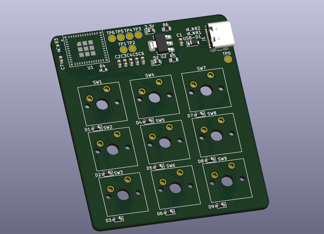
This document describes the intended design and features.
| Qty | Value | Footprint | References |
|---|---|---|---|
| 9 | 1N4148-0805 | Diode_SMD:D_SOD-323_HandSoldering | D1, D2, D3, D4, D5, D6, D7, D8, D9 |
| 9 | SW_Push | Button_Switch_Keyboard:SW_Cherry_MX_1.00u_PCB | SW1, SW2, SW3, SW4, SW5, SW6, SW7, SW8, SW9 |
| 7 | TestPoint | TestPoint:TestPoint_Pad_D2.0mm | TP0, TP1, TP2, TP3, TP4, TP5, TP6 |
| 6 | 100nF | Capacitor_SMD:C_0603_1608Metric_Pad1.08x0.95mm_HandSolder | C1, C2, C3, C4, C5, C6 |
| 3 | LOGO | LOGO | G***, G***, G*** |
| 2 | 10k | Resistor_SMD:R_0603_1608Metric_Pad0.98x0.95mm_HandSolder | R3, R4 |
| 2 | 3.3k | Resistor_SMD:R_0805_2012Metric_Pad1.20x1.40mm_HandSolder | R5, R6 |
| 2 | 5.5k | Resistor_SMD:R_0603_1608Metric_Pad0.98x0.95mm_HandSolder | R1, R2 |
| 2 | LED | Diode_SMD:D_0805_2012Metric_Pad1.15x1.40mm_HandSolder | PWR1, PWR2 |
| 1 | 1uF | Capacitor_SMD:C_0603_1608Metric_Pad1.08x0.95mm_HandSolder | C7 |
| 1 | AZ1117CH2-3.3 | Package_TO_SOT_SMD:SOT-223-3_TabPin2 | U2 |
| 1 | ESP32-C6-MINI-1 | RF_Module:ESP32-C6-MINI-1 | U1 |
| 1 | USB_C_Receptacle_USB2.0_16P | Connector_USB:USB_C_Receptacle_GCT_USB4105-xx-A_16P_TopMnt_Horizontal | J1 |
It measures 60 × 70.3 mm and has 2 copper layers, 1.6 mm thick.
46 parts, built around the ESP32-C6-MINI-1. The full list of its parts is on this page, with links to each part's symbol and footprint where PCBKit's library has them.
From the AccelRanger/macropad repository on GitHub, at the commit this page was made from: the board is PCB/macropad.kicad_pcb and its schematic PCB/macropad.kicad_sch. PCBKit opens the board in the browser, with nothing to install.
Its repository publishes it under the Apache-2.0 licence: you may reuse it on that licence's terms (keep the author's notice, and for a copyleft licence share your changes alike).


tomasmcguinness/esp32-modbus-serial-adapter
The hardware folder contains a KiCad PCB design, designed around the ESP32-C6-MINI-1. Both the antenna and non-antenna (U1) versions will work here due to the location of the ESP32.


jernej13/Tempic
Small solarpowered ESP32 based indoor/outdoor wifi weather station.

tomasmcguinness/matter-esp32-mbus-adapter
An ESP32-C6 adapter board for wired M-Bus (EN 13757) meters, with firmware examples that expose meter readings to a Matter fabric over Thread.

wildsystems/ws-uc06
Custom ESP32-C6 development board with power input protection, relay outputs, opto-isolated I/O, NTC sensor input, and JTAG debugging. Designed as a DIY-friendly controller base.

Enderman8843/Carbon
Carbon is an open-source indoor air quality sensing board designed for accurate VOC, temperature, and humidity monitoring.