2 layers125 × 185 mm

 abyrne55/dual-input-load-share-controller
KiCAD schematics for a "12VDC Dual-Input Load Share Controller with USB Monitoring" PCB
Dual input load share controller is an open-source printed circuit board by abyrne55, from the abyrne55/dual-input-load-share-controller repository on GitHub, published under the Unlicense licence. It is a 2-layer board of 70 × 57 mm with 46 parts on 37 nets, routed with 382 tracks and 50 vias.
It is built around the IPP055N08NF2SAKMA1-JSM, PJ-082BH and AI-1223-TWT-5V-5-R, with the PN2222A, USB-B1HSB6 and USBLC6-4SC6 among its other parts. Its parts include 12 capacitors, 11 resistors, 8 connectors, 4 ICs and 3 transistors. It belongs with the PIC boards of this library.


A not-yet-tested dual-supply load-sharing PCB built around the LTC4370 in KiCAD. I'm planning on using it to combine two 60W PoE splitters into a fault-tolerant 12 VDC power supply for my homelab (i.e., the NAS, router, modem, switches, MoCA adapters, and NUCs/SBCs that live in my apartment's power-outlet-free closet). I designed it for a nominal load of 60W (so that a single UPS-backed PoE line can sustain the load during a power outage, at least for long enough for the sensitive equipment to gracefully power down) and a max load of 160W. YMMV.
[!TIP]
<ad>PCBWay very kindly provided me with free PCB prototyping/manufacturing services for this personal project. Their support was a huge part of why I decided to polish up the original prototype into the full-blown PCB you see here. Consider checking them out.</ad>
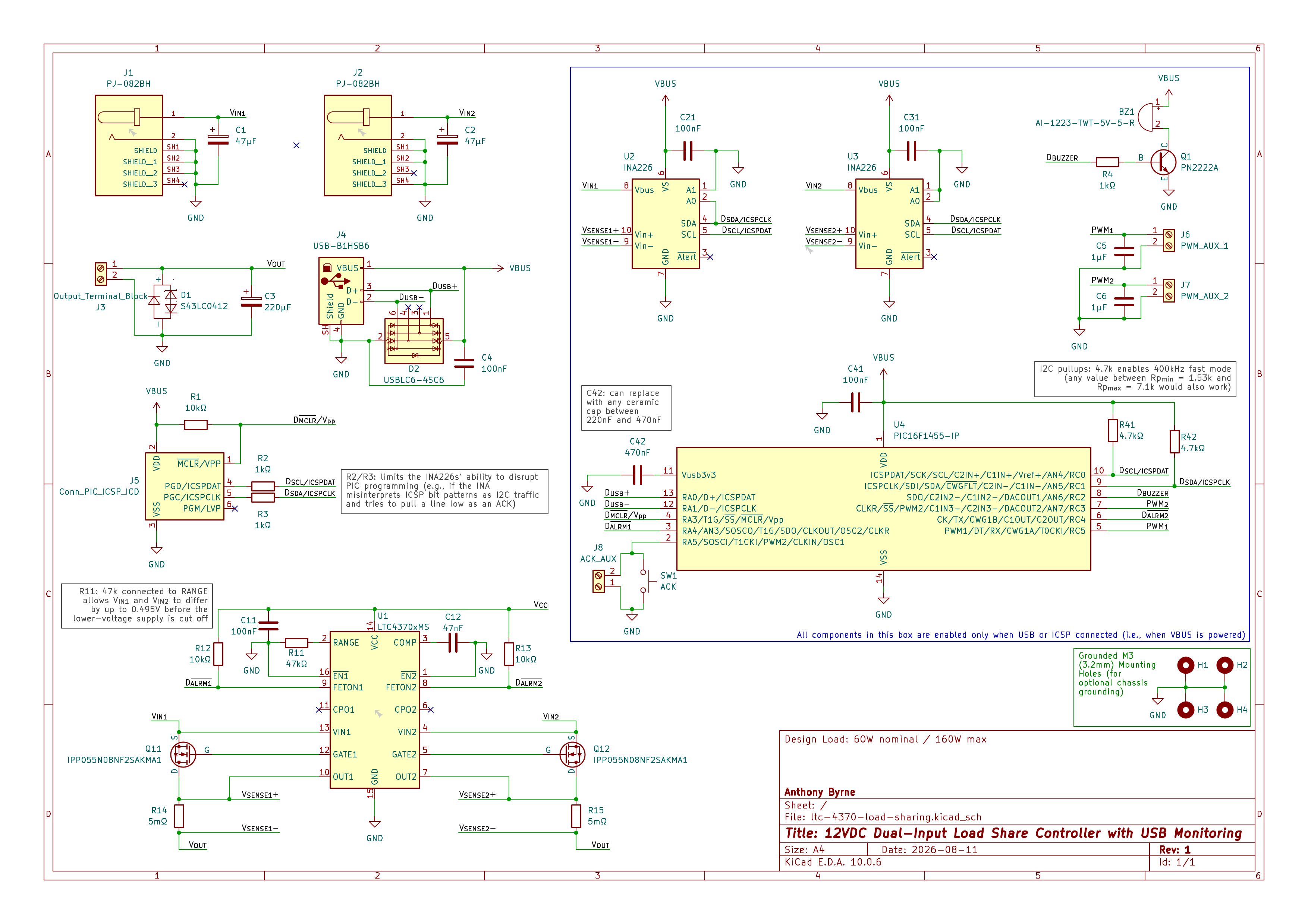
The design is based on the reference schematics in the LTC4370's datasheet. I tweaked the capacitor values and MOSFET models to match what I had on-hand or could find on DigiKey. All components in the blue box are optional but enable USB-based monitoring; design is based off of my UPS-emulating USB dongle. I'll also be monitoring output voltage (J3) using my non-linear voltmeter.


Public domain. See UNLICENSE for more details. No warranties; I'm an amateur electrical engineer at best.
| Qty | Value | Footprint | References |
|---|---|---|---|
| 5 | 100nF | Capacitor_THT:C_Disc_D5.0mm_W2.5mm_P5.00mm | C4, C11, C21, C31, C41 |
| 4 | MountingHole_Pad | MountingHole:MountingHole_3.2mm_M3_Pad_Via | H1, H2, H3, H4 |
| 3 | 10kΩ | Resistor_THT:R_Axial_DIN0207_L6.3mm_D2.5mm_P10.16mm_Horizontal | R1, R12, R13 |
| 3 | 1kΩ | Resistor_THT:R_Axial_DIN0207_L6.3mm_D2.5mm_P10.16mm_Horizontal | R2, R3, R4 |
| 2 | 1µF | Capacitor_THT:C_Disc_D5.0mm_W2.5mm_P5.00mm | C5, C6 |
| 2 | 4.7kΩ | Resistor_THT:R_Axial_DIN0207_L6.3mm_D2.5mm_P10.16mm_Horizontal | R41, R42 |
| 2 | 47µF | Capacitor_THT:CP_Radial_D5.0mm_P2.50mm | C1, C2 |
| 2 | 5mΩ | BR3FB5L00:RES_BR3_STP | R14, R15 |
| 2 | INA226 | Package_SO:TSSOP-10_3x3mm_P0.5mm | U2, U3 |
| 2 | IPP055N08NF2SAKMA1 | Package_TO_SOT_THT:TO-220-3_Vertical | Q11, Q12 |
| 2 | PJ-082BH | PJ-082BH:SAMESKY_PJ-082BH | J1, J2 |
| 1 | 220µF | Capacitor_THT:CP_Radial_D6.3mm_P2.50mm | C3 |
| 1 | 470nF | Capacitor_THT:C_Disc_D5.0mm_W2.5mm_P5.00mm | C42 |
| 1 | 47kΩ | Resistor_THT:R_Axial_DIN0207_L6.3mm_D2.5mm_P10.16mm_Horizontal | R11 |
| 1 | 47nF | Capacitor_THT:C_Disc_D5.0mm_W2.5mm_P5.00mm | C12 |
| 1 | ACK | Button_Switch_THT:SW_PUSH_6mm | SW1 |
| 1 | ACK_AUX | TerminalBlock_Phoenix:TerminalBlock_Phoenix_PT-1,5-2-5.0-H_1x02_P5.00mm_Horizontal | J8 |
| 1 | AI-1223-TWT-5V-5-R | AI-1223-TWT-5V-5-R:XDCR_AI-1223-TWT-5V-5-R | BZ1 |
| 1 | Conn_PIC_ICSP_ICD | Connector_PinHeader_2.54mm:PinHeader_1x06_P2.54mm_Vertical | J5 |
| 1 | LTC4370xMS | Package_SO:MSOP-16_3x4.039mm_P0.5mm | U1 |
| 1 | Output_Terminal_Block | TerminalBlock_CUI:TerminalBlock_CUI_TB007-508-02_1x02_P5.08mm_Horizontal | J3 |
| 1 | PIC16F1455-IP | Package_DIP:DIP-14_W7.62mm_Socket | U4 |
| 1 | PN2222A | Package_TO_SOT_THT:TO-92_Inline | Q1 |
| 1 | PWM_AUX_1 | TerminalBlock_Phoenix:TerminalBlock_Phoenix_PT-1,5-2-5.0-H_1x02_P5.00mm_Horizontal | J6 |
| 1 | PWM_AUX_2 | TerminalBlock_Phoenix:TerminalBlock_Phoenix_PT-1,5-2-5.0-H_1x02_P5.00mm_Horizontal | J7 |
| 1 | S43LC0412 | S43LC0412:SOT-143_Handsoldering_Diode | D1 |
| 1 | USB-B1HSB6 | Connector_USB:USB_B_OST_USB-B1HSxx_Horizontal | J4 |
| 1 | USBLC6-4SC6 | Package_TO_SOT_SMD:SOT-23-6_Handsoldering | D2 |

nmatic00/max1491-4wire-ohmmeter
My first KiCAD project. 4 Wire Kelvin Ohmmeter based on MAX1491 ADC.

Sooraj21s/High-Volt-Radiation-Detect-PCB
A PCB that converts the radiatoin detected by the geiger tube captured as milli volts to a high voltage by opamp & a buzzer is also provided in the module that triggers when the detected voltage reaches a certain…

Fiberprinter/fiberprinter-electronics
Fiberelectronics Control every pulse, master every micron


Rivercraft911/R-01_Raster_Laser_Projector
Red, blue and green lasers combine through two dichroc mirrors and bounce off a spinning polygon mirror, which each mirror facet makes one scanline.

robertpuccinelli/microfluidic_controller_reviewer_copy
This repository contains supplementary information and resources for a microfluidic controller platform based on the plfluidic Python module.
It measures 70 × 57 mm and has 2 copper layers, 1.6 mm thick.
46 parts, built around the IPP055N08NF2SAKMA1-JSM, PJ-082BH, AI-1223-TWT-5V-5-R and PN2222A. The full list of its parts is on this page, with links to each part's symbol and footprint where PCBKit's library has them.
From the abyrne55/dual-input-load-share-controller repository on GitHub, at the commit this page was made from: the board is dual-input-load-share-controller.kicad_pcb and its schematic dual-input-load-share-controller.kicad_sch. PCBKit opens the board in the browser, with nothing to install.
Its repository publishes it under the Unlicense licence: you may reuse it on that licence's terms (keep the author's notice, and for a copyleft licence share your changes alike).