Skip to the content
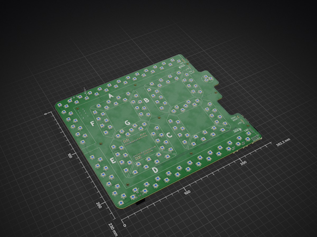
2 layers262.2 × 230 mmArenaTimer, the printed circuit board in 3D

Open Source Area Timer for combat robotics

Size
262.2 × 230 mm
Copper layers
2
Thickness
1.6 mm
Parts
224
Nets
208
Pads
849
Tracks, vias
1,614, 264
Pours
5
Routed
Yes
KiCad
KiCad 10.0 (file 20260206)
Created
26 Nov 2024
Updated
22 Oct 2026

Overview

ArenaTimer is an open-source printed circuit board by WannaBAcoder, from the WannaBAcoder/ArenaTimer repository on GitHub. It is a 2-layer board of 262.2 × 230 mm with 224 parts on 208 nets, routed with 1,614 tracks and 264 vias.

It is built around the WS2812B, BSS138 and CEM-1203(42), with the PJ-082BH among its other parts. Its parts include 173 diodes, 21 connectors, 9 resistors, 7 capacitors and 2 transistors.

Main components

4

README

readme.md

⏱️ Event Match Timer & Lockout System

An open-source, ESP32-based event and match timer platform featuring wireless remote integration, with web interface.


🚀 Getting Started

1. Hardware Orientation & Powering

  • Orientation Flexibility: The timer can be configured to operate in either horizontal orientation. If your mounting or power cable strategy requires it, you can flip the included hanging bracket to the opposite side and enable Invert Display in the web settings to route the power cable from above.
  • Power Requirements: Connect the timer using the provided power supply.

⚠️ CRITICAL: Only use 5V power supplies capable of delivering at least 60W. Applying a voltage higher than 5V will permanently damage the hardware.

2. Initial Wi-Fi & Web UI Setup

  1. Boot Sequence: Upon power-up, the display initializes with dashes (--:--) and the border will blink, indicating it is attempting to connect to the last saved Wi-Fi network.
  2. Access Point (AP) Mode: If the network is unavailable (or during first-time setup), the timer switches to AP mode, broadcasting its own network:
    • SSID: TimerSetup
    • Password: 12345678
  3. Connecting to the UI: * Connect your phone, tablet, or computer to the TimerSetup network.
    • Locate the timer's IP address in your device's network connection settings (this process varies by operating system).
    • Open a web browser and enter the IP address to access the control interface.

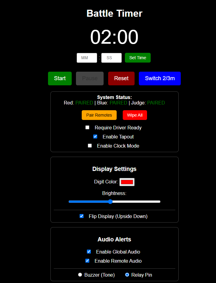
Web Control Interface Dashboard

Note: The local AP interface is identical to the network interface. If no external Wi-Fi network is available at your venue, you can run the timer in this standalone mode completely offline.

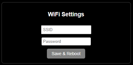
  1. Station Mode (Optional): To connect the timer to an existing venue Wi-Fi network, use the configuration section at the bottom of the webpage to save your local SSID and Password.

Wireless Remotes Layout


⚙️ Configuration & Features

🎮 Wireless Remotes & Pairing

The system supports three battery-powered wireless remotes: one Main Controller and two Driver Ready/Tap-Out buttons (Red vs. Blue).

Wireless Remotes Layout

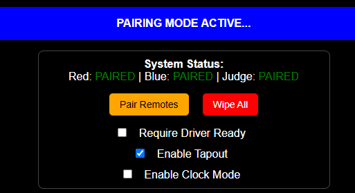
  • Pairing Procedure: Remotes must be paired before deployment. Click Pair Remote in the Web UI to enter binding mode, turn on the remote, and press any button. The timer will automatically exit binding mode, and the Web UI status will update to Paired. Repeat independently for each remote.
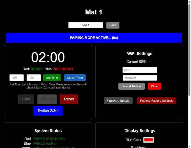
    • Pairing Timeout: Binding mode automatically cancels itself after 15 seconds if no remote responds (with a live countdown shown on screen), rather than hanging indefinitely until a reboot.
  • Driver Ready Lockout: Enabling the Require Driver Ready checkbox prevents a match from starting until both driver remotes register a "Ready" state - the Start button itself grays out while waiting, and the ready state for each side is shown directly under the countdown.
    • Visual Indicators: The physical white border indicates overall readiness. Individual Red/Blue illumination confirms when each respective driver has ready-ed up.
  • Tap-Out Functionality: Even if the pre-match lockout is disabled, the driver remotes function by default as tap-out indicators. Pressing them during a match triggers a unique tap-out animation and audio effect (can be toggled off via the checkbox).

Pairing countdown, ready status, and per-timer naming

📻 ESP-NOW and LoRa Remotes, Side by Side

Newer timer boards carry an onboard LoRa radio alongside the original ESP-NOW remote support - both run at the same time, in the same firmware image. That means a single timer can have, say, Red paired to an older ESP-NOW remote while Blue and Judge are paired to newer LoRa remotes, so a LoRa-capable board can go into service before every remote in the field is replaced.

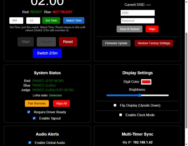
  • Per-Role Binding: Each of Red, Blue, and Judge is paired independently, and the System Status panel shows exactly which radio each one is bound through - PAIRED (ESP-NOW), PAIRED (LoRa), or PAIRED (LoRa+ESP-NOW) if the same role has been bound on both.
  • Automatic Hardware Detection: On boards without the LoRa radio installed, the firmware detects its absence at boot (shown as LoRa radio: Not detected) and simply runs ESP-NOW only, rather than wasting startup time retrying a radio that isn't there.

Dual ESP-NOW/LoRa pairing status, Match Time, and WiFi management

🔗 Multi-Timer Sync (Web-Based)

Running several mats off one set of remotes already works by pairing the same remote to each timer directly (above) - but for anything triggered from the web page (start/pause/reset, time-select, colors, brightness, audio, ready/tapout settings), pair two timers together over WiFi so clicking a button on one applies to both.

  • Setup: Open the Multi-Timer Sync panel, enter the other timer's local IP address (shown on its own page as My IP), and click Sync. Everything that timer currently has configured pushes over immediately, so both units start in agreement instead of drifting until the next change.
  • What Syncs: Match control, match time, display color/brightness/flip, audio settings, ready-required, tap-out, and clock mode. Remote button presses are not relayed this way - they already reach every timer that remote is directly paired to, with no extra setup needed.
  • One-Directional by Default: Sync only pushes outward from whichever timer's web page you clicked on - pair both timers to each other's IP if you want either one to be able to drive the other.
  • Naming Timers: Give each unit a short label (e.g. "Mat 1") at the top of its page - shown in the browser tab too - so it's obvious which page you're looking at when several are open side by side.

⏱️ Match Time vs. Set Time

Two different buttons next to the manual MM:SS entry handle two different needs:

  • Set Time: A one-off override for just the upcoming match. Pressing Reset afterward falls back to whatever the standing default already was (the 2/3-minute preset, or a previously-set Match Time).
  • Match Time: Sets a new standing default - Reset keeps returning to this duration until the unit reboots (it isn't saved permanently, so a custom one-off event length doesn't silently become the new default forever). The Switch 2/3m button still overrides it either way.

🕐 Clock Mode

Toggle Enable Clock Mode (in Display Settings) to repurpose the digit display as a wall clock when the timer is idle between matches. The web page itself keeps showing whatever match time was last active (dimmed, since it isn't live) - the physical display is what shows the actual time.

🔊 Audio Options

  • Global Toggle: Easily enable or disable all system audio via the web panel.
  • Output Routing: Switch between the onboard piezo beeper or a dedicated relay output used to switch larger external horn circuits, PA systems, or specialized lighting.
  • Attention Horn: The Main Controller features a dedicated button to manually trigger the sound effects to grab the attention of competitors or spectators.

🔒 Operational Lockout

To prevent accidental mid-match disruption, most configuration options, adjustments, and web buttons are automatically disabled while the timer is actively running.


🛠️ Assembly Process (Electronics Kits)

For users assembling the hardware from the DIY electronics kits, follow this general framework. Refer to the project BOM.md for exact hardware sizing, screw counts, and component sourcing links.

1. 3D Printed Frame Selection

Choose the frame variant that best fits your 3D printer's build volume:

  • Small Printers: Cut down to fit standard build plates. Requires more assembly hardware and time but maximizes accessibility.
  • Medium Printers (H2s/H2d Optimized): A balanced approach featuring lower part counts and optimized print times.
  • Large Printers: Designed specifically for large-format platforms like the Elegoo Orange Storm Giga.

2. Print Settings & Materials

  • Main Frame: Print in PETG for superior mechanical strength and thermal resilience during high-temperature transport or storage.
    • Walls: 4–6 perimeters
    • Infill: 15–25% Gyroid
  • Lenses: All frame variations share the same lens files. Print them with enough top/bottom layers to ensure the front face prints completely solid to optimize light diffusion and visual clarity.

🧠 Advanced Development & Limitations

📡 RF Limitations & Best Practices

The timer utilizes an ESP32 module with a printed trace antenna; remotes utilize ESP8266 modules over ESP-NOW, or on newer timer boards, dedicated LoRa radios (see ESP-NOW and LoRa Remotes, Side by Side above) - both with printed antennas.

  • Range & Interference: While highly reliable in tested arena layouts (e.g., SEMO), performance can degrade at extreme distances or in environments experiencing heavy 2.4 GHz spectrum congestion (crowded Wi-Fi, heavy radio traffic).
  • Upgrades: If your venue demands extreme range, the hardware can be modified to use variants featuring external SMA antennas. Reach out if you need assistance engineering a solution.
  • Running Multiple Timers: Pair a single set of remotes to multiple timers by repeating the pairing process on each one (above), and/or bind timers to each other for web-triggered actions - see Multi-Timer Sync above.

💻 Firmware Upgrades & Exposed I/O

  • Over-The-Air (OTA) Updates: Firmware updates can be flashed seamlessly without opening the enclosure. Navigate to http://<your-timer-ip>/update to access the ElegantOTA interface, where you can drag-and-drop compiled .bin updates.
  • Restore Factory Settings: A dedicated button wipes all remotes, WiFi credentials, sync target, and display/audio settings in one step, then reboots - useful for repurposing a unit or ruling out a stale setting during troubleshooting. WiFi credentials alone can also be wiped independently (Wipe, next to Save & Reboot) without touching anything else.
  • Hardware Expansion: Additional I/O pins are deliberately exposed near the internal ESP32 module. Advanced users can open the case and solder directly to these lines to integrate custom addressable LED strips, sensors, or physical inputs.

⚡ ESD Precautions & LED Repair

⚡ CAUTION: The internal PCBs contain components sensitive to Electrostatic Discharge (ESD). Handle bare board assemblies with care during assembly or modifications.

  • Common Failure Mode: If an ESD event occurs, a single addressable LED in the display chain may burn out. Because the LEDs are wired in series, if one LED fails, all subsequent data down the chain is blocked, causing the rest of the display past that point to drop out.
  • Support: If you experience an LED failure during assembly or firmware hacking, reach out—these are repairable, and I can guide you through jumping or replacing the compromised pixel. Note that failures have only occurred during loose bench development; fully enclosed units have proven resilient during regular live event usage.

Parts

224
QtyValueFootprintReferences
171WS2812BLED_SMD:LED_WS2812B_PLCC4_5.0x5.0mm_P3.2mmD1, D10, D11, D12, D13, D14, D15, D112, D113, D114, D115, D116, D117, D118, D154, D155 +155
9MountingHoleMountingHole:MountingHole_3.2mm_M3H1, H2, H3, H4, H5, H6, H7, H8, H9
7100nFCapacitor_SMD:C_0402_1005MetricC1, C2, C3, C4, C5, C6, C7
710kResistor_SMD:R_0402_1005MetricR3, R4, R5, R6, R7, R8, R9
2100KResistor_SMD:R_0402_1005MetricR2, R10
2BSS138Package_TO_SOT_SMD:SOT-323_SC-70Q1, Q2
2Conn_01x15_SocketConnector_PinSocket_2.54mm:PinSocket_1x15_P2.54mm_VerticalJ15, J16
2SPARE GNDConnector_PinHeader_2.54mm:PinHeader_1x04_P2.54mm_VerticalJ20, J21
2WAGOWAGO_2060-452_998-404:2060-452_998-404J13, J14
11N4007, SMADiode_SMD:D_SMAD40
11N4148WS, SOD323Diode_SMD:D_SOD-323D41
15VConnector_PinHeader_2.54mm:PinHeader_1x04_P2.54mm_HorizontalJ5
15VConnector_PinSocket_2.54mm:PinSocket_1x04_P2.54mm_HorizontalJ7
1Blue ready-upConnector_JST:JST_EH_S2B-EH_1x02_P2.50mm_HorizontalJ1
1CEM-1203(42)Buzzer_Beeper:Buzzer_TDK_PS1240P02BT_D12.2mm_H6.5mmBZ1
1Conn_01x02_PinConnector_PinHeader_2.54mm:PinHeader_1x02_P2.54mm_HorizontalJ3
1Conn_01x02_SocketConnector_PinSocket_2.54mm:PinSocket_1x02_P2.54mm_HorizontalJ2
1Conn_01x06_PinConnector_JST:JST_EH_S6B-EH_1x06_P2.50mm_HorizontalJ9
1G5V-2_SplitRelay_THT:Relay_DPDT_Omron_G5V-2K1
1GNDConnector_PinSocket_2.54mm:PinSocket_1x04_P2.54mm_HorizontalJ6
1GNDConnector_PinHeader_2.54mm:PinHeader_1x04_P2.54mm_HorizontalJ4
1LOGOSEMO:SEMOG***
1PJ-082BHSAMESKY_PJ-082BH:SAMESKY_PJ-082BHJ8
1Red ready-upConnector_JST:JST_EH_S2B-EH_1x02_P2.50mm_HorizontalJ10
1SPARE 3.3VConnector_PinHeader_2.54mm:PinHeader_1x04_P2.54mm_VerticalJ18
1SPARE 5VConnector_PinHeader_2.54mm:PinHeader_1x04_P2.54mm_VerticalJ19
1SPARE IOConnector_PinHeader_2.54mm:PinHeader_1x04_P2.54mm_VerticalJ17
1SPARE_IOConnector_PinHeader_2.54mm:PinHeader_1x06_P2.54mm_VerticalJ11
1Screw_Terminal_01x03TerminalBlock:TerminalBlock_MaiXu_MX126-5.0-03P_1x03_P5.00mmJ12

More from WannaBAcoder/ArenaTimer

5
  • 2 layers86.6 × 54.5 mmESP32 Lora, the printed circuit board in 3D

    ESP32 Lora

    WannaBAcoder/ArenaTimer

    Open Source Area Timer for combat robotics

    42 parts3
  • 2 layers60 × 100 mmTimerRemote, the printed circuit board in 3D

    TimerRemote

    WannaBAcoder/ArenaTimer

    Open Source Area Timer for combat robotics

    33 parts3
  • 2 layers60 × 100 mmButtonBoard, the printed circuit board in 3D

    ButtonBoard

    WannaBAcoder/ArenaTimer

    Open Source Area Timer for combat robotics

    19 parts3
  • 2 layers60 × 100 mmReadyButtonBoard, the printed circuit board in 3D

    ReadyButtonBoard

    WannaBAcoder/ArenaTimer

    Open Source Area Timer for combat robotics

    11 parts3
  • 2 layers41.9 × 44.5 mmOldReadyButtonBoard, the printed circuit board in 3D

    OldReadyButtonBoard

    WannaBAcoder/ArenaTimer

    Open Source Area Timer for combat robotics

    7 parts3

Similar boards

  • 2 layers200 × 120 mmPlytka v2, the printed circuit board in 3D

    Plytka v2

    tmierzwa/WICI

    Otwarty system łączności awaryjnej (Reticulum/LXMF, 869 MHz)

    152 parts4
  • 2 layers60 × 90 mmVideoconsola, the printed circuit board in 3D

    Videoconsola

    aindustriosa/Video-consola-ESP32

    Unha videoconsola portátil feita por nós, e un SDK para aprender a programar os teus propios xogos nela.

    33 partsGPL-3.0
  • 2 layers55.9 × 68.6 mmPCB Chair tracker, the printed circuit board in 3D

    PCB Chair tracker

    josarcsal/chair_tracker_repository

    Proyecto TFG Chair Tracker

    13 parts
  • 2 layers99 × 99 mm2nd mainboard pcb, the printed circuit board in 3D

    2nd mainboard pcb

    Fiberprinter/fiberprinter-electronics

    Fiberelectronics Control every pulse, master every micron

    132 parts4
  • 2 layers126 × 107 mmIcon, the printed circuit board in 3D

    Icon

    devguardio/icon

    The internets RGB panel

    122 parts1Apache-2.0
  • 4 layers100 × 100 mmPcb AMY, the printed circuit board in 3D

    Pcb AMY

    Rivercraft911/R-01_Raster_Laser_Projector

    Red, blue and green lasers combine through two dichroc mirrors and bounce off a spinning polygon mirror, which each mirror facet makes one scanline.

    159 parts1
  • 2 layers70 × 57 mmDual input load share controller, the printed circuit board in 3D

    Dual input load share controller

    abyrne55/dual-input-load-share-controller

    KiCAD schematics for a "12VDC Dual-Input Load Share Controller with USB Monitoring" PCB

    46 partsUnlicense
  • 2 layers50.4 × 69 mmPLRD1 24ChRelayDriver, the printed circuit board in 3D

    PLRD1 24ChRelayDriver

    robertpuccinelli/microfluidic_controller_reviewer_copy

    This repository contains supplementary information and resources for a microfluidic controller platform based on the plfluidic Python module.

    86 partsCC-BY-4.0

Questions

How big is the ArenaTimer PCB?

It measures 262.2 × 230 mm and has 2 copper layers, 1.6 mm thick.

What parts does the ArenaTimer use?

224 parts, built around the WS2812B, BSS138, CEM-1203(42) and PJ-082BH. The full list of its parts is on this page, with links to each part's symbol and footprint where PCBKit's library has them.

Where can I download the ArenaTimer KiCad files?

From the WannaBAcoder/ArenaTimer repository on GitHub, at the commit this page was made from: the board is PCB Files/DisplayBoard/ArenaTimer.kicad_pcb and its schematic PCB Files/ButtonBoard/ButtonBoard.kicad_sch. PCBKit opens the board in the browser, with nothing to install.

Can I use the ArenaTimer design in my own project?

Its repository states no licence, so its author keeps all rights: ask WannaBAcoder before reusing the design.