SkyEar
A pocket radio that listens to lightning thousands of miles away.
Lightning strikes somewhere on Earth dozens of times every second, and every strike gives off a burst of very-low-frequency (VLF) radio. SkyEar picks those bursts up with a wire antenna, cleans them up, and plays them through headphones. You hear distant storms as crackling ("sferics"), and sometimes as eerie falling whistles ("whistlers"): lightning signals that went out into space, followed Earth's magnetic field, and came back down.
I'm building it for Hack Club Half Life (Week 1: PCB design).
How it works
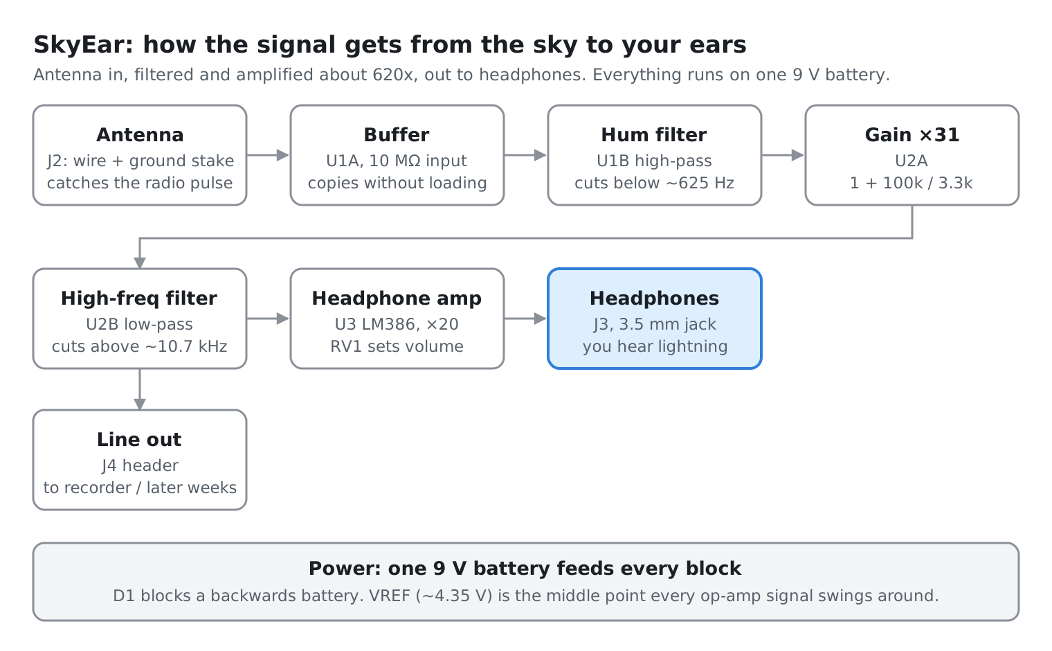
SkyEar is a fully analog circuit: two op-amp chips, one headphone amp chip, and a 9 V battery. The signal goes through it in this order:
| Stage | Part | What it does |
|---|
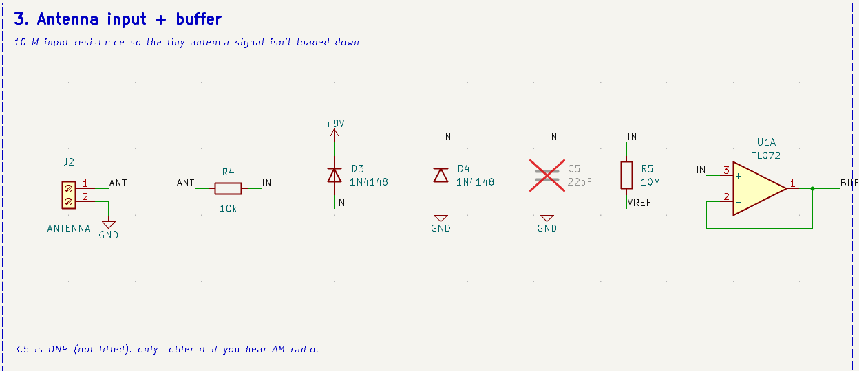
| Antenna input | J2, R4, D3, D4 | A wire antenna plus a ground stake. The diodes dump static from the antenna safely into the power rails. |
| Buffer | U1A (TL072), R5 = 10 MΩ | A short antenna acts like a tiny capacitor (~10–30 pF), so it can barely push any current. The 10 MΩ input and a JFET op-amp copy the signal without draining it. |
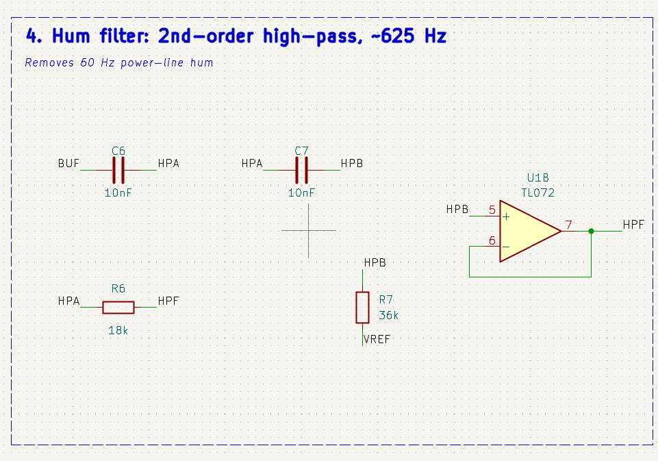
| Hum filter | U1B, C6, C7, R6, R7 | 2nd-order high-pass at ~625 Hz. Power lines put out 60 Hz hum that's way louder than lightning on another continent, so this cuts it. |
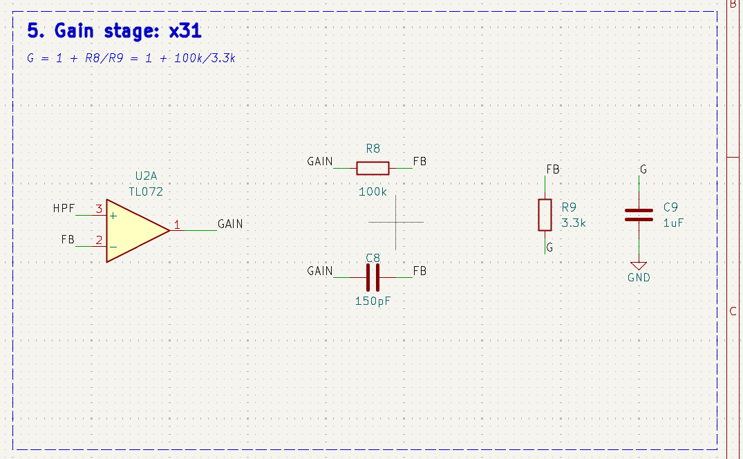
| Gain | U2A, R8, R9 | Amplifies by 1 + 100k / 3.3k ≈ 31. |
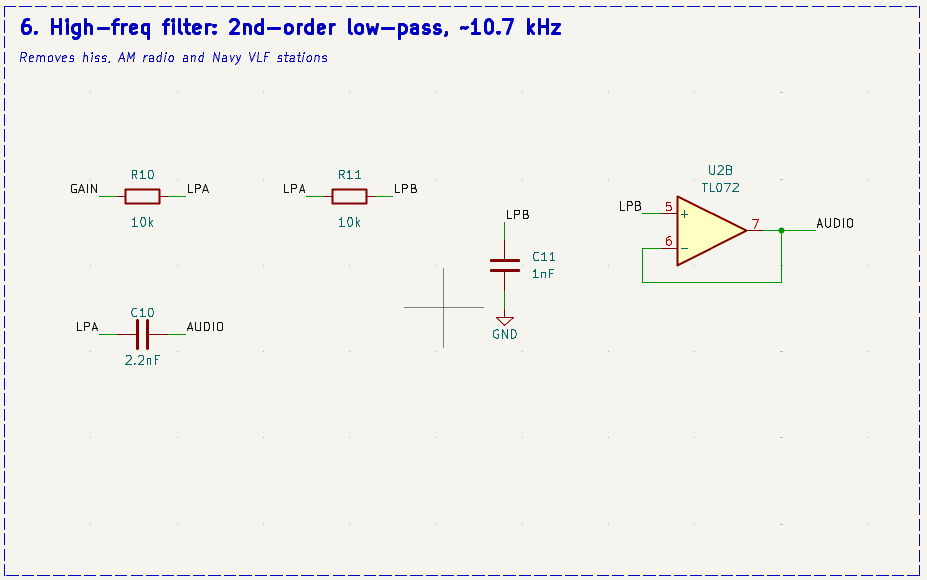
| High-frequency filter | U2B, R10, R11, C10, C11 | 2nd-order low-pass at ~10.7 kHz. Cuts hiss, AM radio, and the Navy's VLF transmitters (~20–25 kHz). |
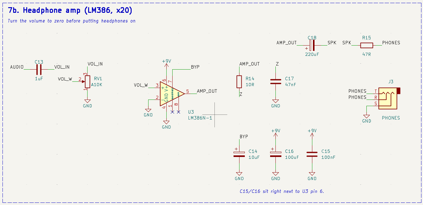
| Headphone amp | U3 (LM386), RV1 | Another 20x, with a volume knob. About 620x total from antenna to ears. |
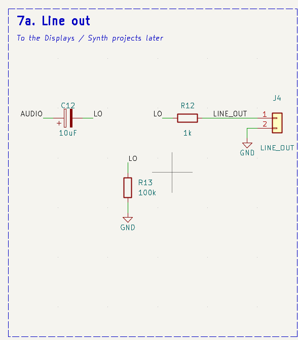
| Line out | J4 | A clean copy of the audio for recording, or for my later Half Life projects. |
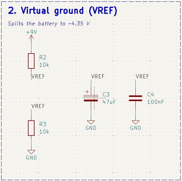
| Power | J1, SW1, D1, R2, R3 | 9 V battery with reverse-polarity protection. R2/R3 make a ~4.35 V "virtual ground" (VREF) so the op-amps can swing both ways on one battery. |
The filter cutoffs come from the standard formulas:
- Input: f = 1 / (2π · 10 MΩ · 30 pF) ≈ 530 Hz
- Hum filter: f = 1 / (2π · 10 nF · √(18 kΩ · 36 kΩ)) ≈ 625 Hz
- Low-pass: f = 1 / (2π · 10 kΩ · √(2.2 nF · 1 nF)) ≈ 10.7 kHz
Schematic
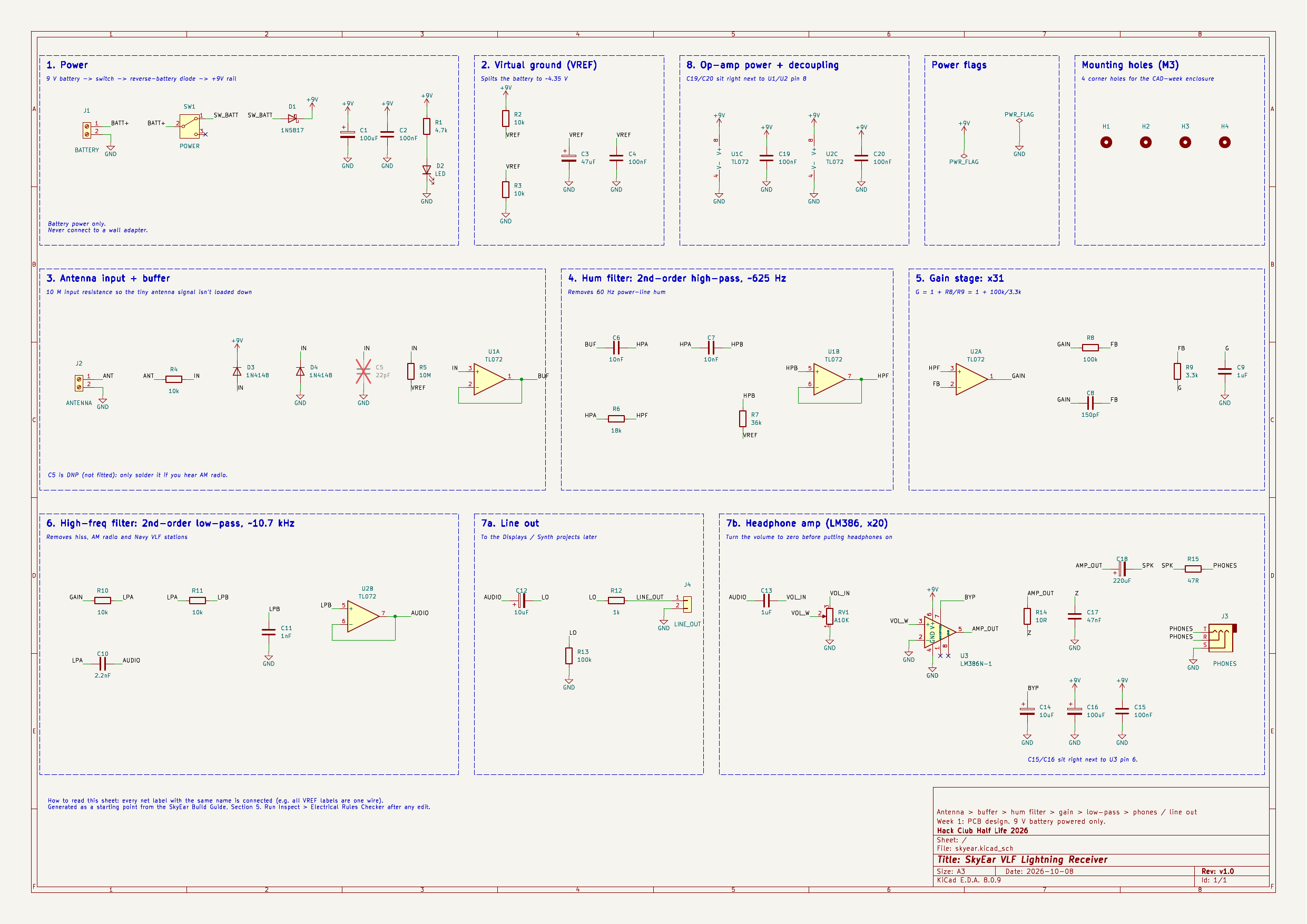
The full KiCad project is in pcb/. Open pcb/skyear.kicad_pro in KiCad 10 (the schematic alone also opens in KiCad 8 and 9). A PDF copy is at pcb/skyear_schematic.pdf.
Block by block
Power: 9 V battery → slide switch → 1N5817 Schottky diode (blocks a backwards battery, only ~0.3 V drop) → +9V rail, with a power LED.
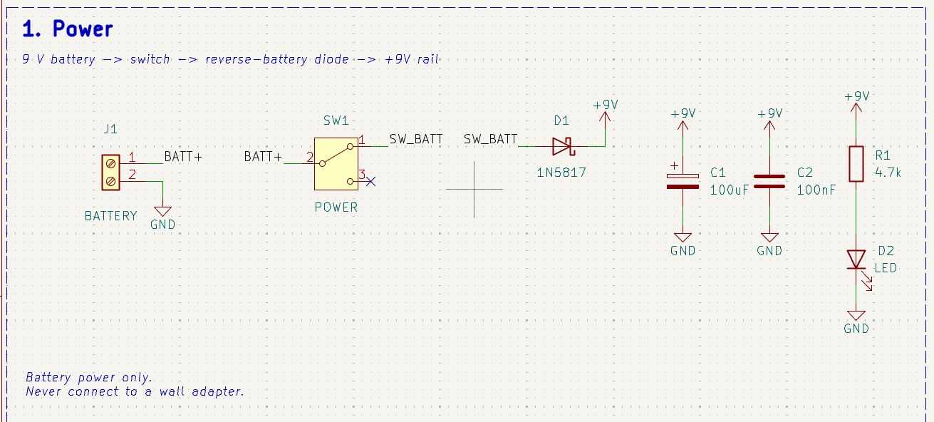
Virtual ground: two 10k resistors split the battery to ~4.35 V so every op-amp signal can swing above and below it.
Antenna input + buffer: R5 is 10 MΩ so the antenna's tiny signal isn't loaded down, and U1A just copies it.
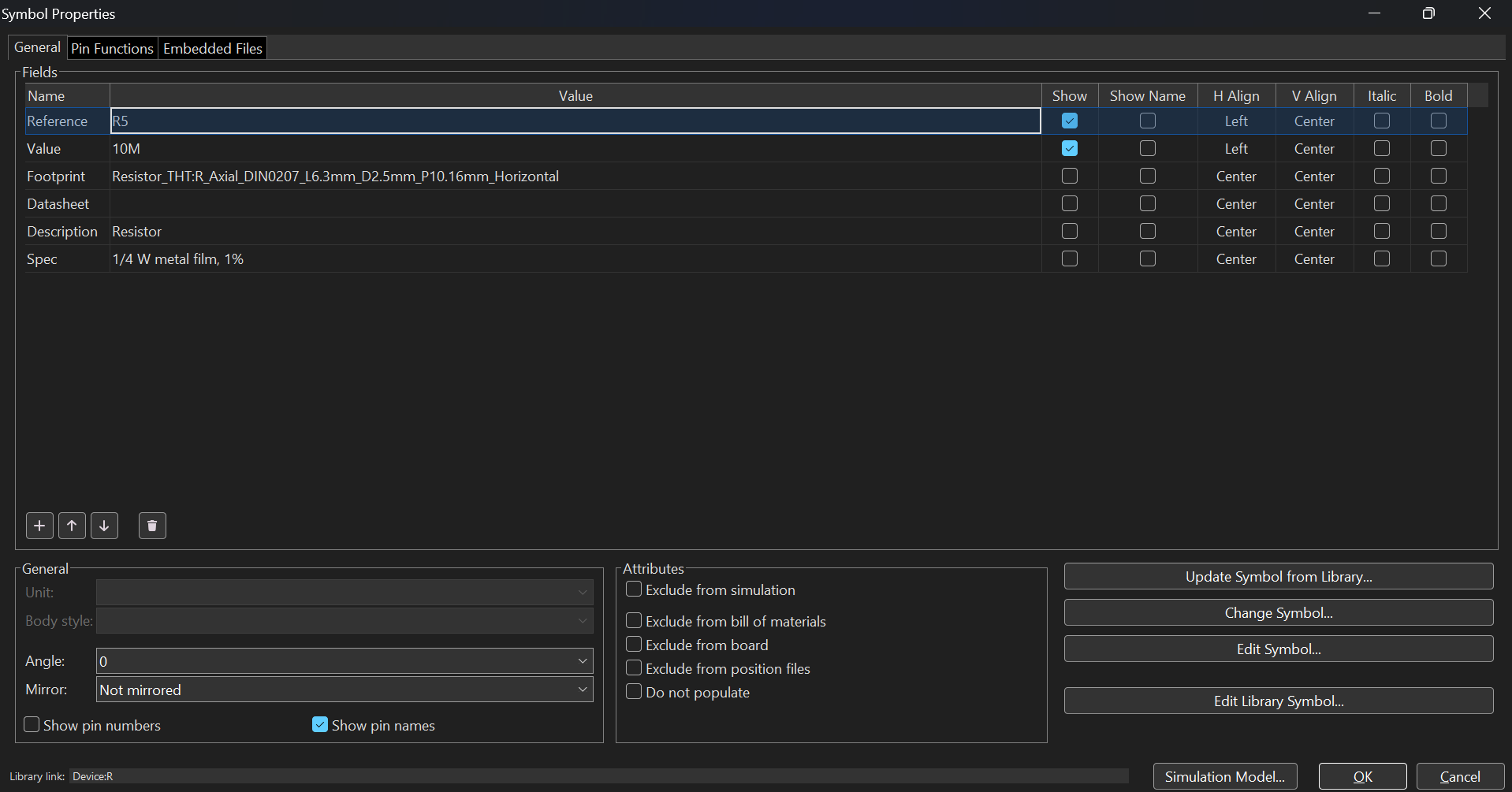
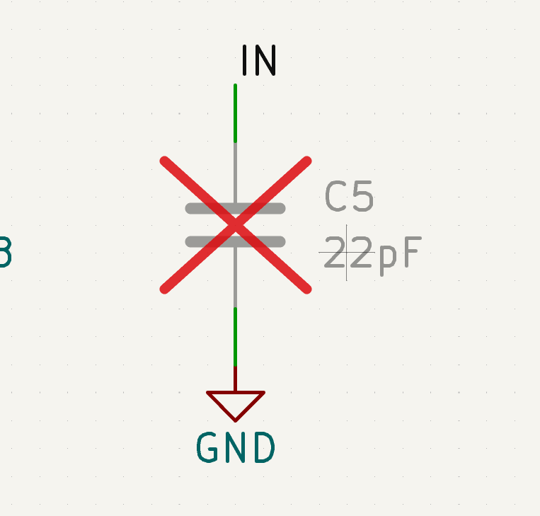
C5 (22 pF) is marked "do not fit". It only gets soldered if AM radio leaks in.
Hum filter: R7 (36k) is exactly twice R6 (18k), which gives a flat Butterworth response with no bump at the cutoff.
Gain stage: x31. C9 keeps DC from being amplified and C8 starts rolling off the highs.
High-frequency filter: cuts everything above ~10.7 kHz.
Line out: a DC-blocked copy of the audio on a 2-pin header.
Headphone amp: LM386 at x20. R14 + C17 keep it from oscillating, C18 blocks DC from the headphones, and R15 limits the max volume. Tip and ring are tied together so both ears get the signal.
Checks
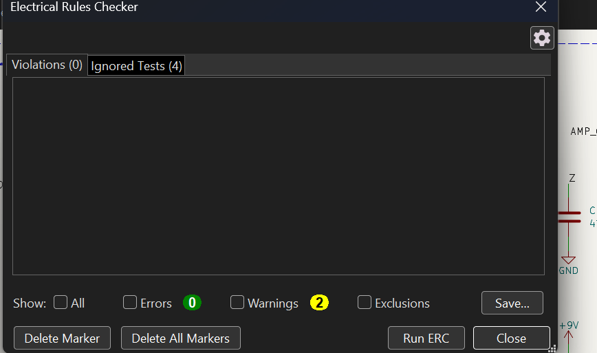
KiCad's Electrical Rules Checker: 0 errors. The 2 warnings are KiCad 10 noticing that the LED and potentiometer symbols have newer artwork in its library; the pins are identical.
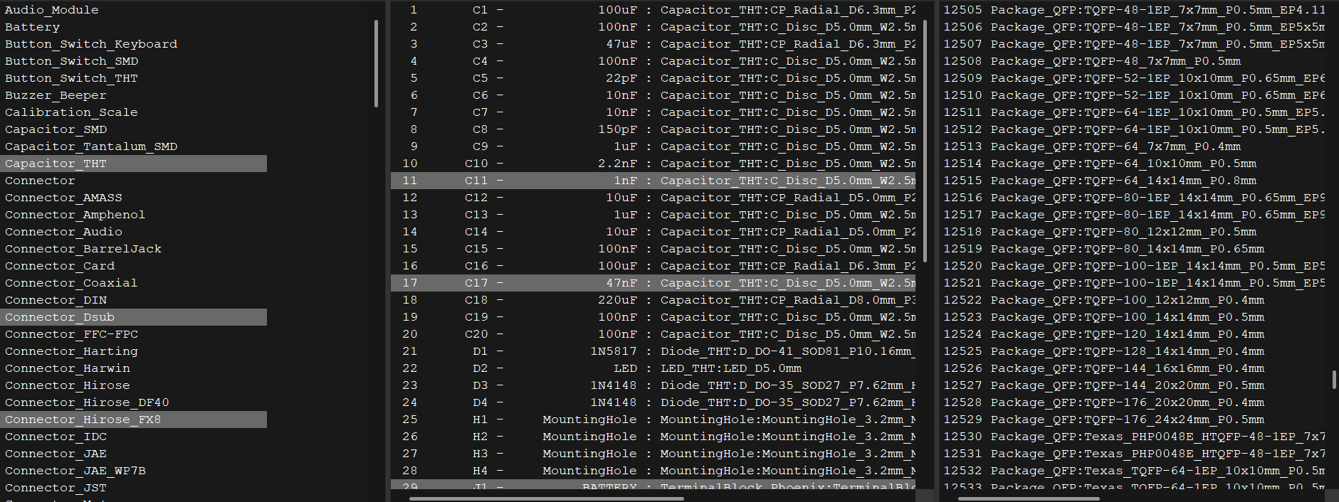
Every part has a footprint assigned:
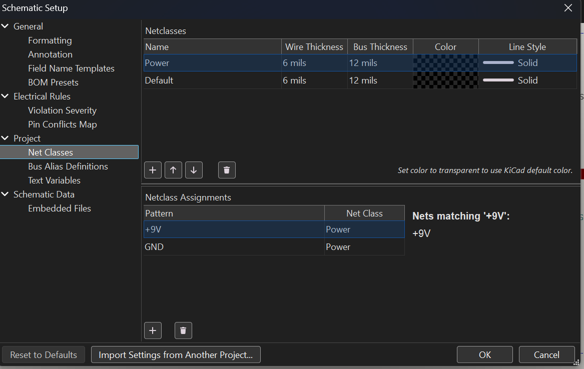
+9V and GND are in a "Power" net class so they get thicker 0.6 mm tracks on the PCB (signals get 0.3 mm):
PCB
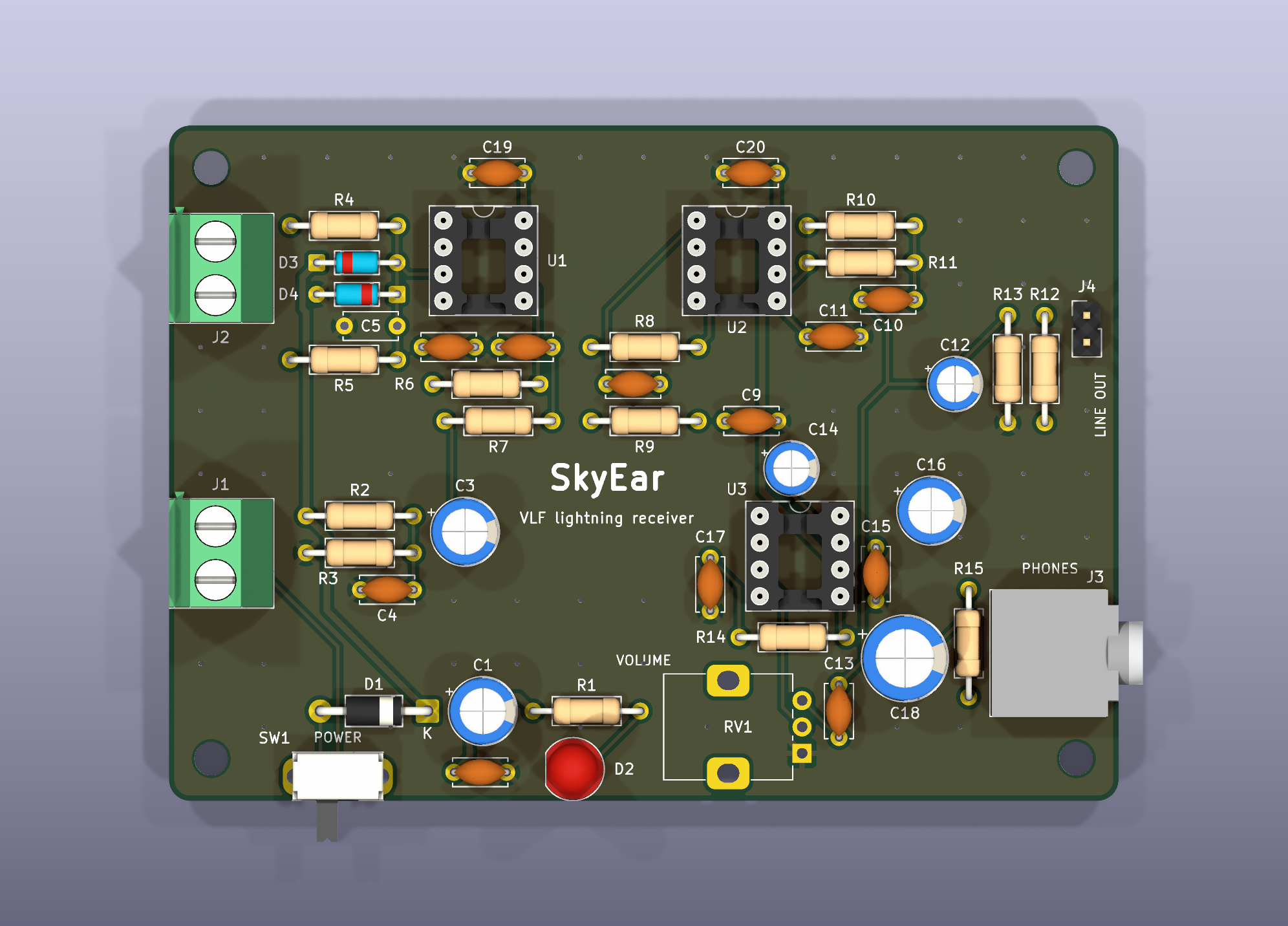
| |
|---|
| Size | 90 × 64 mm, 2 layers, 1.6 mm FR-4, 4 × M3 mounting holes |
| Tracks | 0.3 mm signal, 0.6 mm for +9V and GND, 0.25 mm clearance |
| Ground | GND pour on both layers, stitched together with vias |
| Checks | KiCad DRC: 0 errors, 0 unconnected pads, 0 schematic mismatches (report) |
The 14 DRC warnings are all expected: 13 are connector bodies (terminal blocks, switch, jack, LED) that hang over the board edge on purpose, and 1 is the headphone jack footprint, whose pin slots were widened from 0.4 mm to 0.6 mm because JLCPCB can't make plated slots narrower than 0.5 mm.
Layout
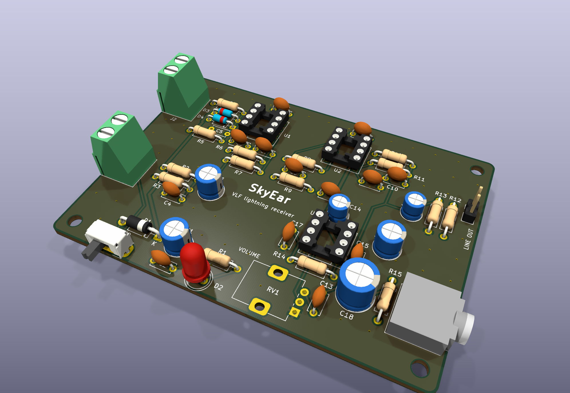
- Signal flows left to right. Antenna in on the left edge, then the buffer (U1), hum filter, gain stage (U2) and low-pass filter across the top. The headphone amp (U3), volume knob and jack are along the bottom right.
- The antenna input is kept tiny. Everything touching the 10 MΩ input node (R4, R5, D3, D4, C5) sits right next to U1 pin 3, because that node picks up hum if its traces are long.
- The headphone amp is far from the input. The LM386's output (the loudest signal on the board) is in the opposite corner from the antenna, so it can't feed back into the input and squeal.
- Every chip has its 100 nF decoupling cap next to its power pin (C19 for U1, C20 for U2, C15 for U3).
- Controls are on the edges. Battery and antenna terminals on the left, power switch and volume on the bottom, headphone jack and line out on the right.
- Routed with Freerouting, then GND pours on both layers.
| Front copper | Back copper |
|---|
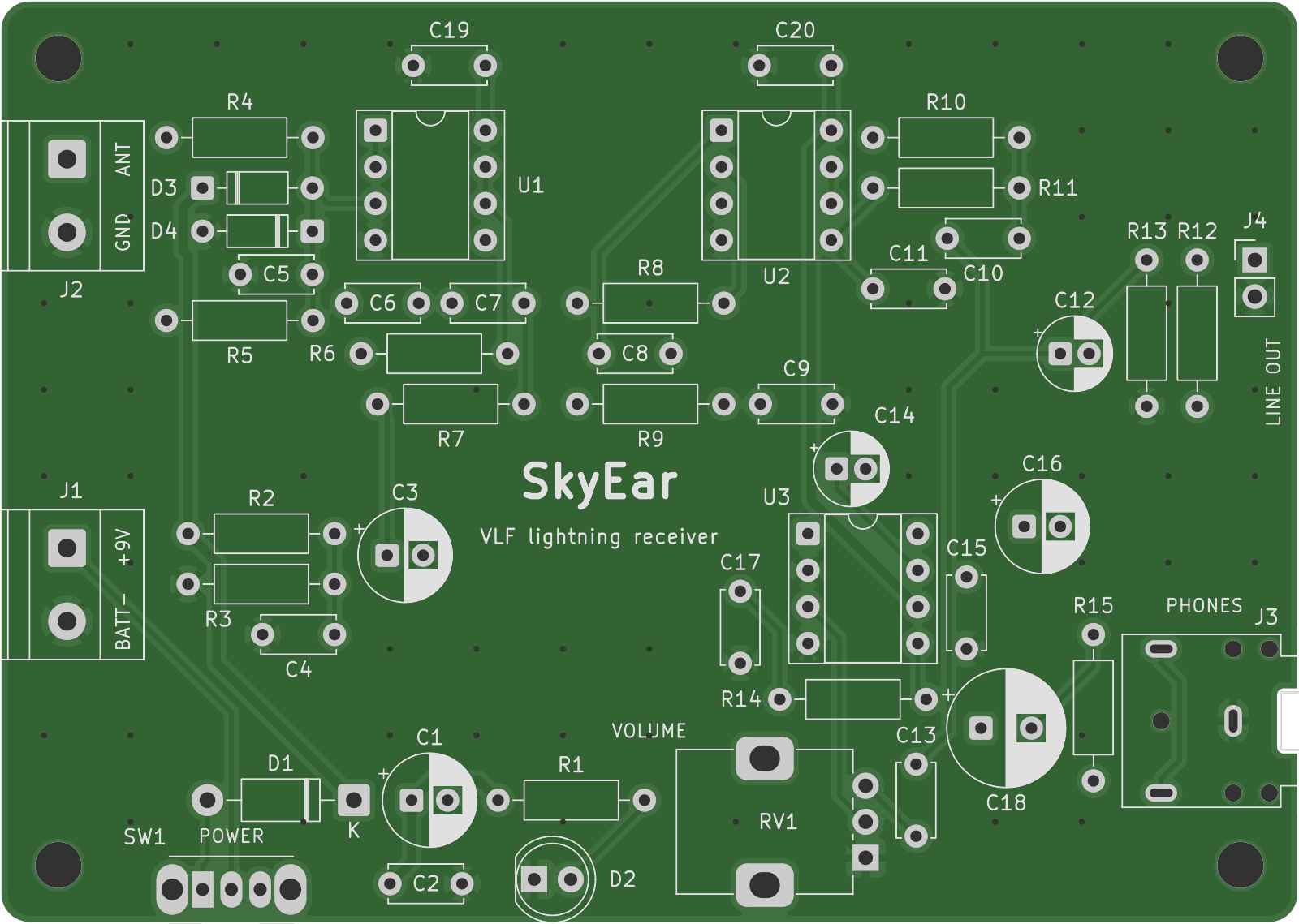 | 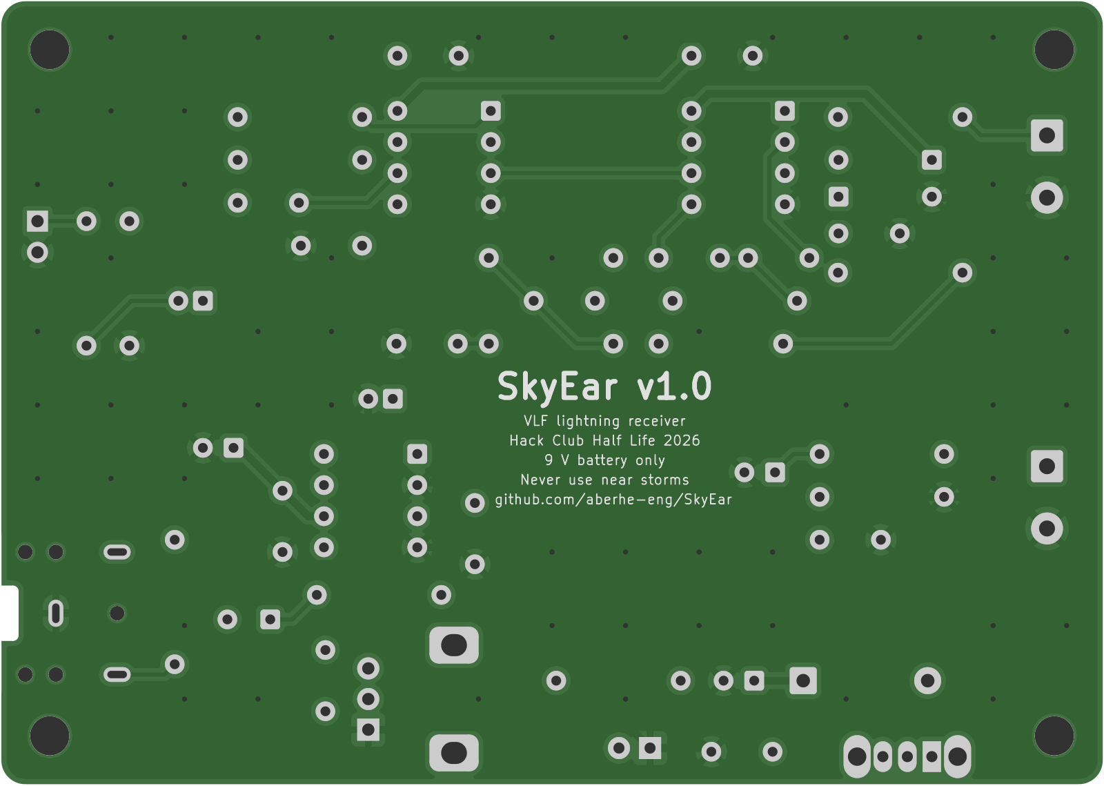 |
The front/back images are rendered straight from the Gerber files, so they show exactly what gets manufactured. The 3D views are from KiCad; the volume pot has no 3D model in KiCad's library, so only its pads show.
Ordering the boards
pcb/skyear_gerbers_jlcpcb.zip is ready to upload at jlcpcb.com/quote (2 layers, 1.6 mm, 5 pcs, any color). The individual Gerber and drill files are in pcb/gerbers/. The board file is pcb/skyear.kicad_pcb (KiCad 10).
Specs
| |
|---|
| Frequency range | ~600 Hz to ~10.7 kHz |
| Power | One 9 V battery, ~10–15 mA |
| Input | Wire antenna + ground stake, 10 MΩ input resistance |
| Outputs | 3.5 mm headphones (with volume), 2-pin line out |
| Parts | 100% through-hole, all chips socketed |
| Board | 2 layers, 90 × 64 mm, 4 × M3 mounting holes |
Parts list
bom.csv has every part with its quantity, real DigiKey price and part number, plus the PCBs from JLCPCB.
- Parts from DigiKey: $29.67 (34 lines, including spares of the cheap parts)
- 5 PCBs from JLCPCB: $2.00
- Parts total: $31.67, before tax and shipping. That's inside the Tier 2 budget ($65).
Not on the list: a 9 V battery (any store) and the antenna wire + ground stake (already owned).
There's no firmware: SkyEar is entirely analog.
Status
Safety
- Never set up the antenna when there are storms nearby. If you can hear thunder, pack up. SkyEar listens to lightning far away, never close.
- Battery power only. Never connect it to a wall adapter.
- Turn the volume to zero before putting headphones on.
- Keep antennas far away from overhead power lines.


