
2 layers65.5 × 30 mm

This is a collection of all the rpositories for the DEFCON screen hat
595pcb is an open-source printed circuit board by abc123me, from the abc123me/screen-hat-defcon repository on GitHub, published under the GPL-2.0 licence. It is a 2-layer board of 80 × 56 mm with 34 parts on 67 nets, routed with 305 tracks and 105 vias.
It is built around the AP63203WU and 74HC595. Its parts include 14 capacitors, 7 ICs, 6 connectors and 1 inductor.


This is a collection of all the rpositories for the DEFCON screen hat
| Name | Description |
|---|---|
| screen-hat-rs | Userspace rust animation app |
| fbgl-rs | Userspace rust graphics library |
| ddmafb | Linux kernel direct DMA framebuffer driver |
| Vivado project | Vivado project for the screen hat |
| Vivado IP | Vivado IP for the screen hat |
| jlbsp | BSP for the screen-hat |
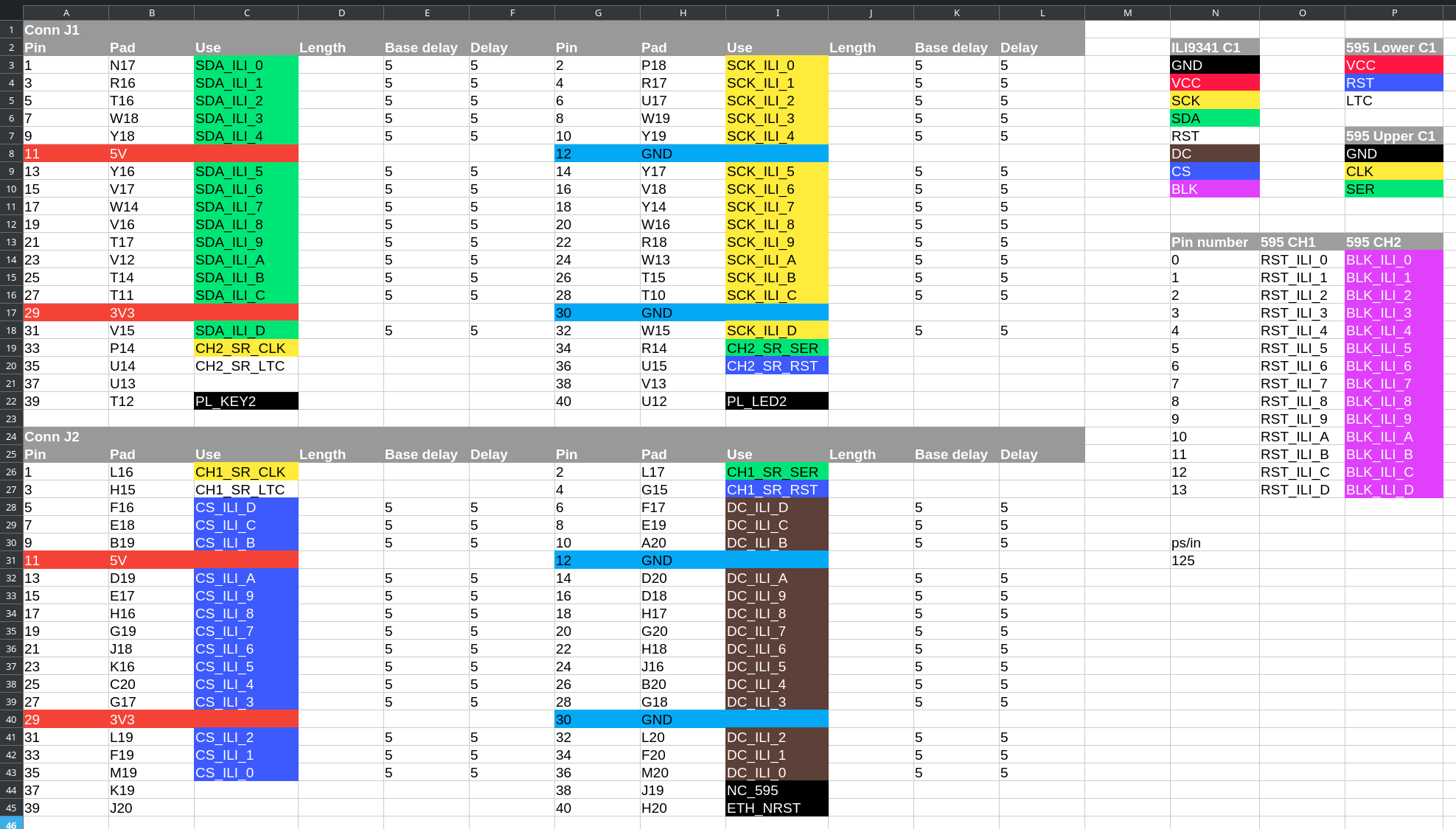
Wiring and other information is contained in the ScreenHat.ods spreadsheet. See the V2 page or picture below for complete information.
The 595pcb KiCAD project is the core GPIO expansion PCB used for backlight and reset
control, gerber files for version 1 of the PCB are inside of 595pcb/grb_v1.zip in this
repository, the BOM for the PCB is below:
| Digikey part no | Quantity | Description |
|---|---|---|
| AP63203WU-7 | 1 | 3.3V 2A Buck converter |
| 74HC595DCT-ND | 6 | 8-Bit Serial-In, Parallel-Out shift register |
| T491S106K010AT | 4 | 10uF, 10V Tantalum capacitor |
| 478-KGM21NR71H104KTCT-ND | 10 | 100nF, 50V MLCC capacitor |
The version 1 on the 595 expansion PCB worked almost perfectly however I suspect it could be improved.
This is a buildroot project, meaning the entire linux kernel and all apps are built from source.
I use Arch btw, but last I checked Fedora is recommended for Linux kernel / Buildroot builds. Arch Linux typically has a GCC version that is too new, meaning you will be fighting GCC - so I wouldn't recommend it.
Buildroot required dependencies
My custom packages all use git so it is also a required package.
fd-find is required for my custom BSP repository and bsp script, if you have not used this unix find replacement, try it!
For any questions on how to modify packages, see the buildroot manual
cd jlbsp)git checkout develop)./bsp setup screen-hat)cd ../builds/screen-hat)JL_SECRET_KEYS repository via make menuconfigmake alldd if=images/sdcard.img of=<my-sd-card> bs=4M oflag=sync status=progressThe jlbsp contains an upgrade script you can use to remotely upgrade the screen hat via make deploy.
The bsps/screen-hat.bsp file contains the IP address that would be used here. You'll also have to
setup SSH keys yourself by adding your SSH keys to the rootfs or enabling root login via SSH.
Serial via the USB UART may also be used, 115200 baud, the username is root, no password.
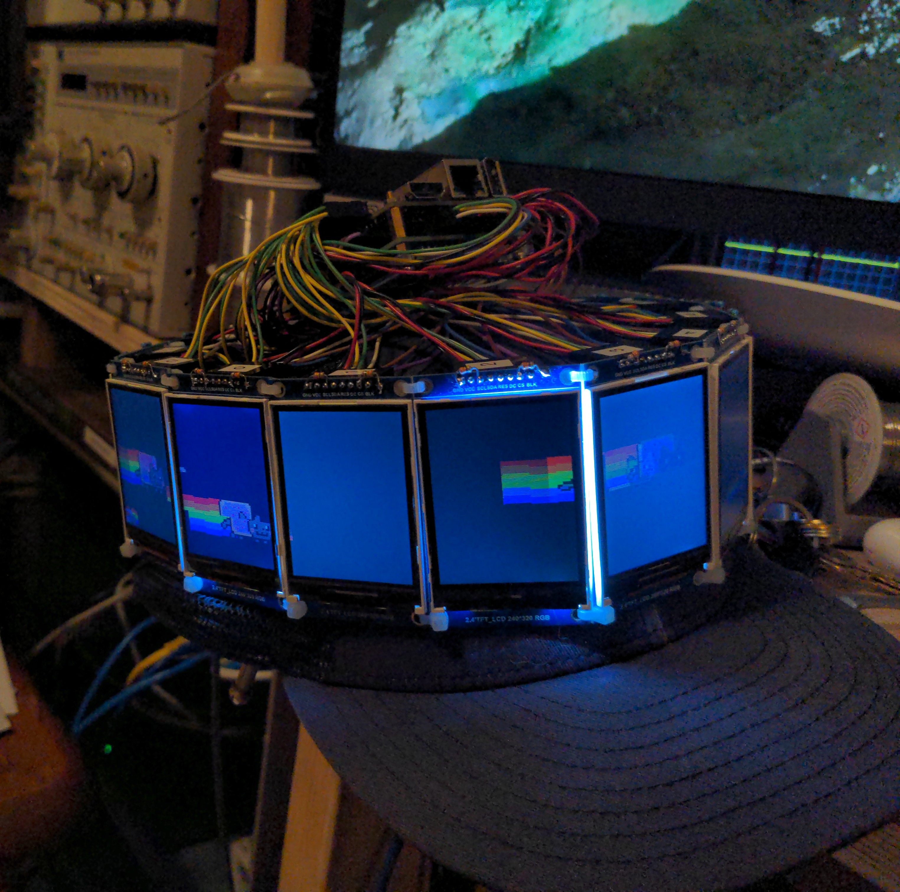
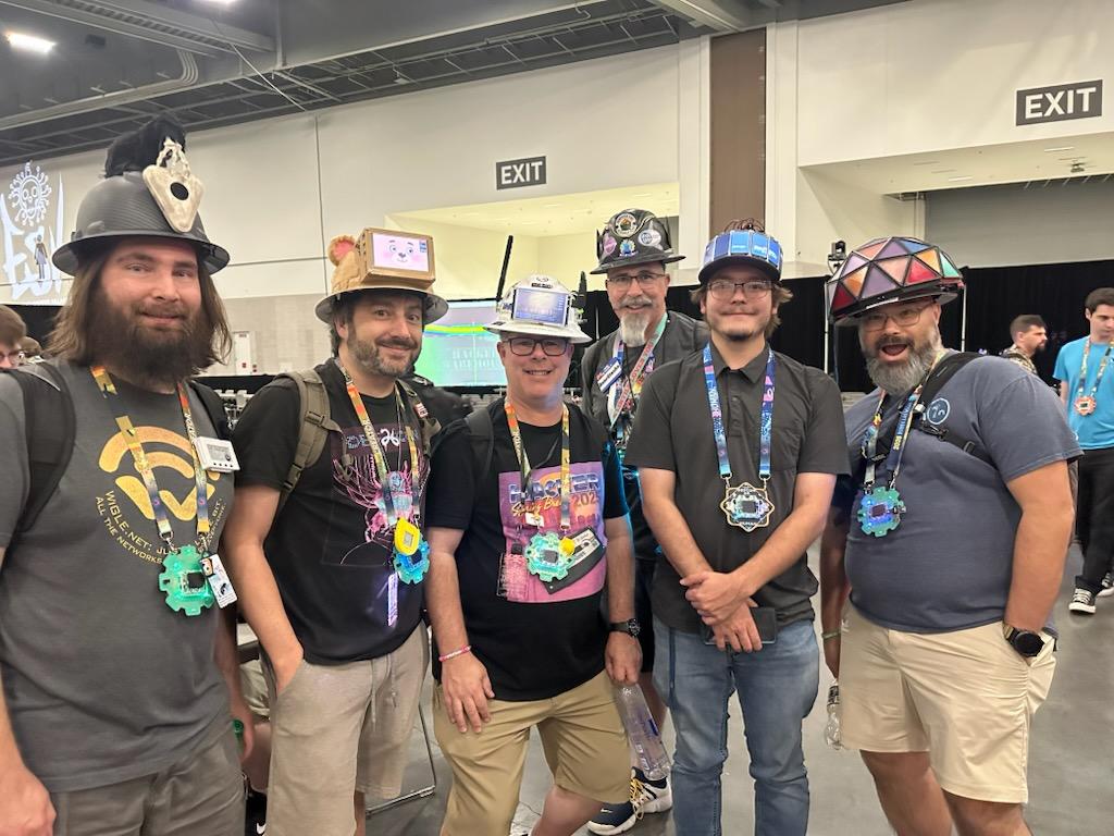
And yes, I know my camera is a potato, and no I will not be upgrading.
| Qty | Value | Footprint | References |
|---|---|---|---|
| 10 | 100nF | Capacitor_SMD:C_0805_2012Metric | C101, C102, C103, C104, C105, C106, C107, C109, C113, C114 |
| 6 | 74HC595 | Package_SO:SOIC-16_3.9x9.9mm_P1.27mm | U101, U102, U103, U104, U105, U106 |
| 4 | 10uF | Capacitor_Tantalum_SMD:CP_EIA-3216-12_Kemet-S | C108, C110, C111, C112 |
| 4 | MountingHole_Pad | MountingHole:MountingHole_2.7mm_M2.5_Pad_Via | H101, H102, H103, H104 |
| 2 | Conn_01x24 | Connector_PinHeader_2.54mm:PinHeader_1x24_P2.54mm_Horizontal | J101, J102 |
| 2 | Conn_02x03_Odd_Even | Connector_PinHeader_2.54mm:PinHeader_2x03_P2.54mm_Horizontal | J105, J106 |
| 2 | Conn_02x08_Odd_Even | Connector_PinHeader_2.54mm:PinHeader_2x08_P2.54mm_Horizontal | J103, J104 |
| 2 | TestPoint | TestPoint:TestPoint_THTPad_1.0x1.0mm_Drill0.5mm | TP_3V101, TP_5V101 |
| 1 | AP63203WU | Package_TO_SOT_SMD:TSOT-23-6 | U107 |
| 1 | L_Ferrite_Small | Inductor_SMD:L_Changjiang_FNR5045S | L101 |
It measures 80 × 56 mm and has 2 copper layers, 1.6 mm thick.
34 parts, built around the AP63203WU and 74HC595. The full list of its parts is on this page, with links to each part's symbol and footprint where PCBKit's library has them.
From the abc123me/screen-hat-defcon repository on GitHub, at the commit this page was made from: the board is 595pcb/595pcb.kicad_pcb and its schematic 595pcb/595pcb.kicad_sch. PCBKit opens the board in the browser, with nothing to install.
Its repository publishes it under the GPL-2.0 licence: you may reuse it on that licence's terms (keep the author's notice, and for a copyleft licence share your changes alike).

punkfab/pcb-corpus
235 real KiCad boards from open-source hardware repositories, prepared as a placement and routing benchmark

AzonInc/Doorman
ESP32-S3 based Intercom Gateway (TCS / Koch / Niko / Scantron / Analogue Systems)

KaiPereira/Cheetah-MX4-Mini
A powerful yet compact 3D printer motherboard that supports TMC stepsticks, fans, heaters, screens and thermistors

FujiNetWIFI/fujinet-hardware
Schematics and design files for FujiNet hardware


lhm0/pd_logger
This repository contains two DIY gadgets to monitor and log USB-C Power Delivery (PD). Both devices are designed to be easy to build, hackable, and useful for makers who want to explore USB-C PD.

Arkos-Engineering/HT-15_hardware
We can split this out into separate repos later, right now its very convenient to have everything here.