2 layers
ErgonomicGamepad
vemcg/ErgonomicGamepad
Custom ergonomic gaming keypad PCB project (KiCad) with a 4x6 key matrix, hot-swap sockets, and USB-C.
86 partsGPL-3.0

 AayushmanDas/AuraClicker
Presentation device
AuraClicker is an open-source printed circuit board by AayushmanDas, from the AayushmanDas/AuraClicker repository on GitHub, published under the MIT licence. It is a 2-layer board of 46 × 90.7 mm with 29 parts on 40 nets, routed with 143 tracks and 40 vias.
It is built around the ESP32-C3-WROOM-02-N4, TMCJ0J106MTRF and RC0603FR-07100KL, with the RC0603FR-0710KL, RC0603FR-07330RL and FRC0603F5101TS among its other parts. Its parts include 9 resistors, 6 capacitors and 5 switches. It belongs with the ESP32 and RISC-V boards of this library.


A compact, battery-powered custom macro-pad and wireless input controller powered by the ESP32-C3 RISC-V microcontroller.
Designed natively in KiCad with end-to-end Design for Manufacturing (DFM) verification, ready for turnkey fabrication and assembly via JLCPCB SMT services.
| 3D PCB Preview | JLCPCB DFM Placement |
|---|---|
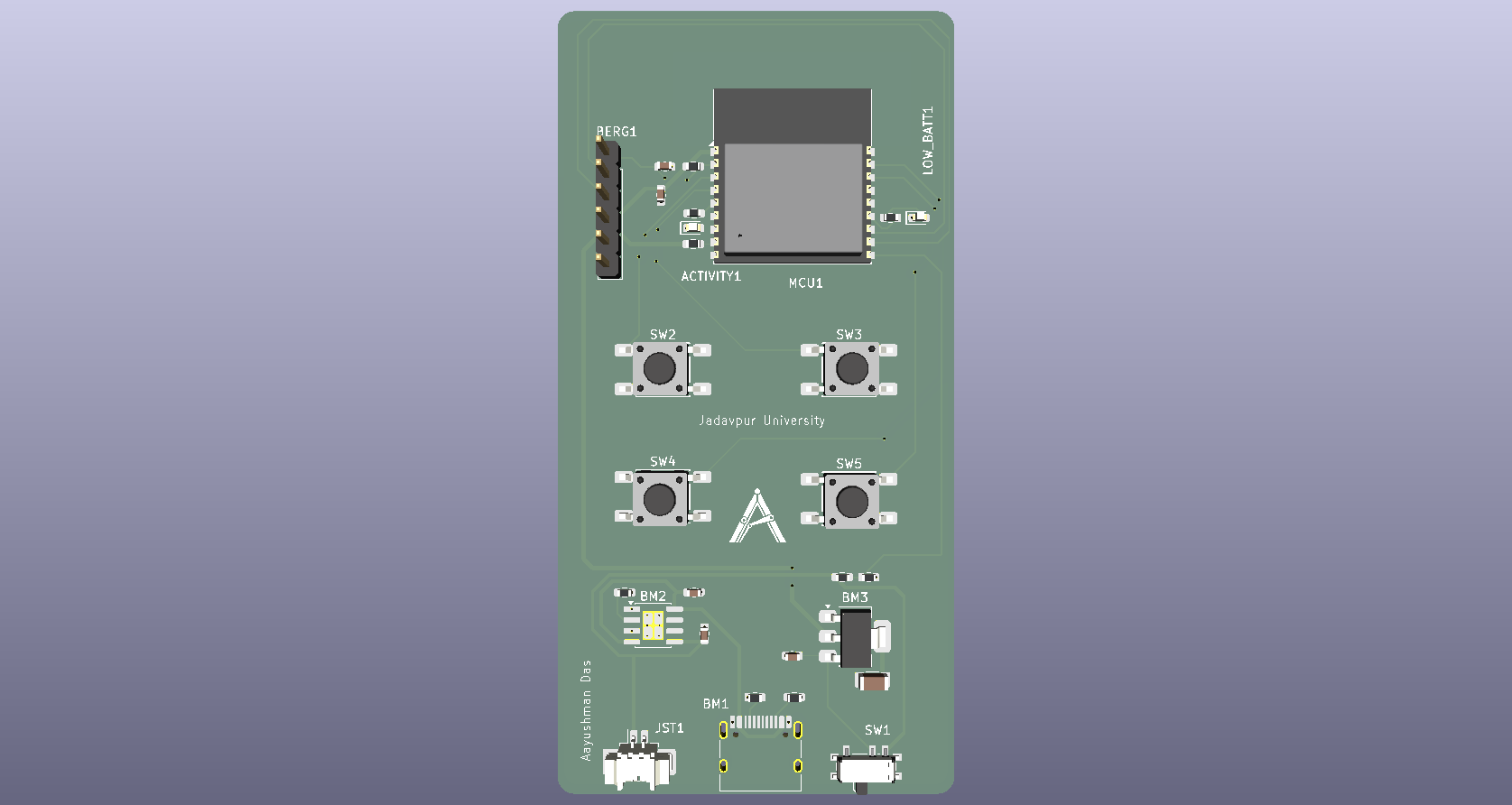 | 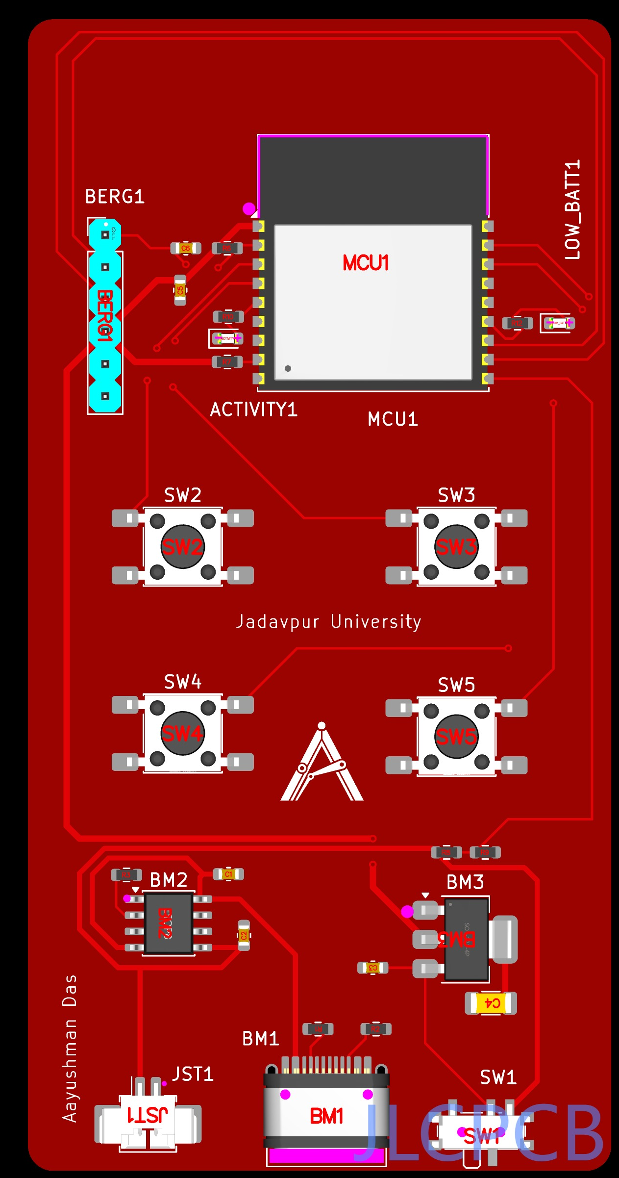 |
SW1).SW2 – SW5) arranged for ergonomic thumb/finger reach.BERG1) for serial programming and debug monitoring.AuraClicker/
├── kicad/ # Raw KiCad project and PCB design files
│ ├── AuraClicker.kicad_pro
│ ├── AuraClicker.kicad_sch
│ ├── AuraClicker.kicad_pcb
│ ├── fp-lib-table
│ └── Team_Antarez_Logo.kicad_mod
│
├── production/ # Fabrication-ready packages & CAD files
│ ├── AuraClicker_Fabrication.zip # Gerber package ready for JLCPCB/PCBWay
│ ├── AuraClicker_BOM.xlsx # Bill of Materials with LCSC part numbers
│ ├── AuraClicker_Placement.xlsx # Pick & Place / Centroid coordinate file (.pos)
│ ├── AuraClicker_schem.pdf # Printable PDF schematic
│ └── AuraClicker_Model.step # Centered-origin 3D CAD STEP model
│
├── media/ # Renders, schematics, and DFM validation captures
├── LICENSE
└── README.md| Peripheral | Reference | Net / Function | Active State |
|---|---|---|---|
| Button 1 | SW2 | Tactile Input | Active Low (Pull-up) |
| Button 2 | SW3 | Tactile Input | Active Low (Pull-up) |
| Button 3 | SW4 | Tactile Input | Active Low (Pull-up) |
| Button 4 | SW5 | Tactile Input | Active Low (Pull-up) |
| Activity LED | D1 / ACTIVITY1 | System Telemetry | Active High |
| Low Batt LED | D2 / LOW_BATT1 | Battery Warning | Active High |
| Power Switch | SW1 | VBAT / VBUS Select | Hardware Cutoff |
| UART Port | BERG1 | TX / RX / GND / 3V3 / DTR / RTS | 3.3V TTL Level |
When placing a PCBA order via JLCPCB, verify the following manual adjustments during the DFM Placement Review step:
BERG1 (1x6 2.54mm Pin Header):
BM1 (USB-C 16-Pin Receptacle):
JST1 (Molex PicoBlade 1.25mm Header):
production/Gerbers_AuraClicker.zip to JLCPCB (FR-4, 1.6mm thickness, standard 2-layer).production/BOM_AuraClicker.csv for the component list.production/CPL_AuraClicker.csv for pick-and-place centroid positions.Reserch\Education\DIY\Entertainment -> DIY Hobby Circuit Board (HS Code: 902300).| Qty | Value | Footprint | References |
|---|---|---|---|
| 3 | 10uF | Capacitor_SMD:C_0603_1608Metric | C1, C2, C3 |
| 2 | 100kohm | Resistor_SMD:R_0603_1608Metric | R8, R9 |
| 2 | 10kohm | Resistor_SMD:R_0603_1608Metric | R6, R7 |
| 2 | 330ohm | Resistor_SMD:R_0603_1608Metric | R10, R12 |
| 2 | 5.1kohm | Resistor_SMD:R_0603_1608Metric | R1, R2 |
| 2 | LED | LED_SMD:LED_0603_1608Metric | ACTIVITY1, LOW_BATT1 |
| 1 | 100nF | Capacitor_SMD:C_0603_1608Metric | C5 |
| 1 | 1uF | Capacitor_SMD:C_0603_1608Metric | C6 |
| 1 | 22uF | Capacitor_SMD:C_1206_3216Metric | C4 |
| 1 | 4.7kohm | Resistor_SMD:R_0603_1608Metric | R3 |
| 1 | AMS1117 | Package_TO_SOT_SMD:SOT-223-3_TabPin2 | BM3 |
| 1 | BLACK | Button_Switch_SMD:SW_Push_1P1T_NO_E-Switch_TL3301NxxxxxG | SW5 |
| 1 | ESC | Button_Switch_SMD:SW_Push_1P1T_NO_E-Switch_TL3301NxxxxxG | SW4 |
| 1 | ESP32-C3 | RF_Module:ESP32-C3-WROOM-02 | MCU1 |
| 1 | FTDI | Connector_PinHeader_2.54mm:PinHeader_1x06_P2.54mm_Vertical | BERG1 |
| 1 | LOGO | AuraClicker:AntarezLogo | G*** |
| 1 | LiPo | Connector_Molex:Molex_PicoBlade_53261-0271_1x02-1MP_P1.25mm_Horizontal | JST1 |
| 1 | NEXT | Button_Switch_SMD:SW_Push_1P1T_NO_E-Switch_TL3301NxxxxxG | SW2 |
| 1 | POWER | Button_Switch_SMD:SW_SPDT_PCM12 | SW1 |
| 1 | PREV | Button_Switch_SMD:SW_Push_1P1T_NO_E-Switch_TL3301NxxxxxG | SW3 |
| 1 | TP4056 | Package_SO:SOIC-8-1EP_3.9x4.9mm_P1.27mm_EP2.41x3.3mm_ThermalVias | BM2 |
| 1 | USB_C_Receptacle_USB2.0_16P | Connector_USB:USB_C_Receptacle_HRO_TYPE-C-31-M-12 | BM1 |
vemcg/ErgonomicGamepad
Custom ergonomic gaming keypad PCB project (KiCad) with a 4x6 key matrix, hot-swap sockets, and USB-C.


Mobilab-AgroTIC/debitdouille
Système pour controler le fonctionnement d'un pulvérisateur

alessandrocardelli/filament-dryer-monitor
ESP32 controller for eSUN eBOX Lite. main is the non-heating SAFE BRING-UP reference; its heater output remains locked OFF.

AndrewCraswell/agency
Native KiCad engineering prototype, separate from the earlier ESP32/tscircuit board. Open usb-scoring-platform.kicadpro in KiCad 10; schematic and PCB are the editable source, with no generator required.


gelotek-com/Anki-In-Hardware
Building a physical flashcard device inspired by Anki and spaced repetition.

It measures 46 × 90.7 mm and has 2 copper layers, 1.6 mm thick.
29 parts, built around the ESP32-C3-WROOM-02-N4, TMCJ0J106MTRF, RC0603FR-07100KL and RC0603FR-0710KL. The full list of its parts is on this page, with links to each part's symbol and footprint where PCBKit's library has them.
From the AayushmanDas/AuraClicker repository on GitHub, at the commit this page was made from: the board is kicad/AuraClicker.kicad_pcb and its schematic kicad/AuraClicker.kicad_sch. PCBKit opens the board in the browser, with nothing to install.
Its repository publishes it under the MIT licence: you may reuse it on that licence's terms (keep the author's notice, and for a copyleft licence share your changes alike).