2 layers189.5 × 204.9 mm
SmartSpin2k Panelized
doudar/SmartSpin2k
Transform your spin bike into a Smart Trainer!
749 parts292GPL-2.0
 aaronnewcomb/Retro-Modem-Board5
This is the PCB I built to be used with the Zmodem project
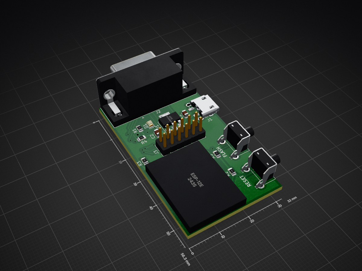
RetroWIFI is an open-source printed circuit board by aaronnewcomb, from the aaronnewcomb/Retro-Modem-Board repository on GitHub, published under the MIT licence. It is a 2-layer board of 32 × 56.3 mm with 21 parts on 27 nets, routed with 224 tracks and 27 vias.
It is built around the ESP-12E and MAX3232ID. Its parts include 7 capacitors, 5 resistors, 3 ICs, 3 connectors and 2 switches. It belongs with the ESP8266 boards of this library.


This is the PCB I built to be used with the Zmodem project

This boards uses an ESP8266 in the form of an ESP-12E/F module along with some simple parts to act as a modem/wifi bridge. It was initially built to be used with this Zmodem project. https://github.com/bozimmerman/Zimodem
3D printable case available here https://www.thingiverse.com/thing:4876405

*All caps and resistors are 0805/2012
| Label | Part |
|---|---|
| C1, C2 | 10uF Capacitor |
| C3 - C7 | .1uF Capacitor |
| D1 | 0805 LED |
| J1 | USB Micro-B socket |
| J2 | 9 Pin Female DSUB 4.94mm Edge Pin Offset |
| J3 | 02x06 Pin Header |
| R1 | 470 Ohm Resistor |
| R2 - R5 | 1K Ohm Resistor |
| SW1, SW2 | Push Button Right Angle |
| U1 | NCP1117ST33T3G |
| U2 | MAX3232 |
| U3 | ESP-12E/F Module |
| Qty | Value | Footprint | References |
|---|---|---|---|
| 5 | .1uF | Capacitor_SMD:C_0805_2012Metric | C3, C4, C5, C6, C7 |
| 4 | 1K | Resistor_SMD:R_0805_2012Metric | R2, R3, R4, R5 |
| 2 | 10uF | Capacitor_SMD:C_0805_2012Metric | C1, C2 |
| 1 | 470 | Resistor_SMD:R_0805_2012Metric | R1 |
| 1 | Conn_02x06 | Connector_PinHeader_2.54mm:PinHeader_2x06_P2.54mm_Vertical | J3 |
| 1 | DB9_Female_MountingHoles | Connector_Dsub:DSUB-9_Female_Horizontal_P2.77x2.84mm_EdgePinOffset4.94mm_Housed_MountingHolesOffset7.48mm | J2 |
| 1 | ESP-12E | footprints:ESP-12E | U3 |
| 1 | FLASH | Button_Switch_THT:SW_Tactile_SKHH_Angled | SW2 |
| 1 | LED | LED_SMD:LED_0805_2012Metric | D1 |
| 1 | MAX3232 | Package_SO:SOIC-16_3.9x9.9mm_P1.27mm | U2 |
| 1 | NCP1117ST33T3G | Package_TO_SOT_SMD:SOT-223 | U1 |
| 1 | RESET | Button_Switch_THT:SW_Tactile_SKHH_Angled | SW1 |
| 1 | USB_B_Micro | footprints:USB_Micro-B_Wuerth_629105150521_power | J1 |
doudar/SmartSpin2k
Transform your spin bike into a Smart Trainer!


zephray/ELTerm
ANSI/VT100-compatible serial terminal built with Raspberry Pi Pico and EL640.480-AM/AG screen


Tjeerdie/SPECTRE
Speeduino compatible engine control unit (ECU) based around black STM32F407VET6 board.

scrapcomputing/ThrottleBlaster
A Turbo circuit with a MHz display that can slow down the CPU speed

cole8888/SRNE-Solar-Charge-Controller-Monitor
Read data from SRNE solar charge controllers.

It measures 32 × 56.3 mm and has 2 copper layers, 1.6 mm thick.
21 parts, built around the ESP-12E and MAX3232ID. The full list of its parts is on this page, with links to each part's symbol and footprint where PCBKit's library has them.
From the aaronnewcomb/Retro-Modem-Board repository on GitHub, at the commit this page was made from: the board is KiCAD/RetroWIFI.kicad_pcb. PCBKit opens the board in the browser, with nothing to install.
Its repository publishes it under the MIT licence: you may reuse it on that licence's terms (keep the author's notice, and for a copyleft licence share your changes alike).