2 layers243.9 × 136.5 mm
Barobord
sadekbaroudi/barobord
I have spent a lot of time and money designing prototypes, testing, developing, etc. Any contributions would be greatly appreciated!
157 parts57

 Zokhoi/5x07
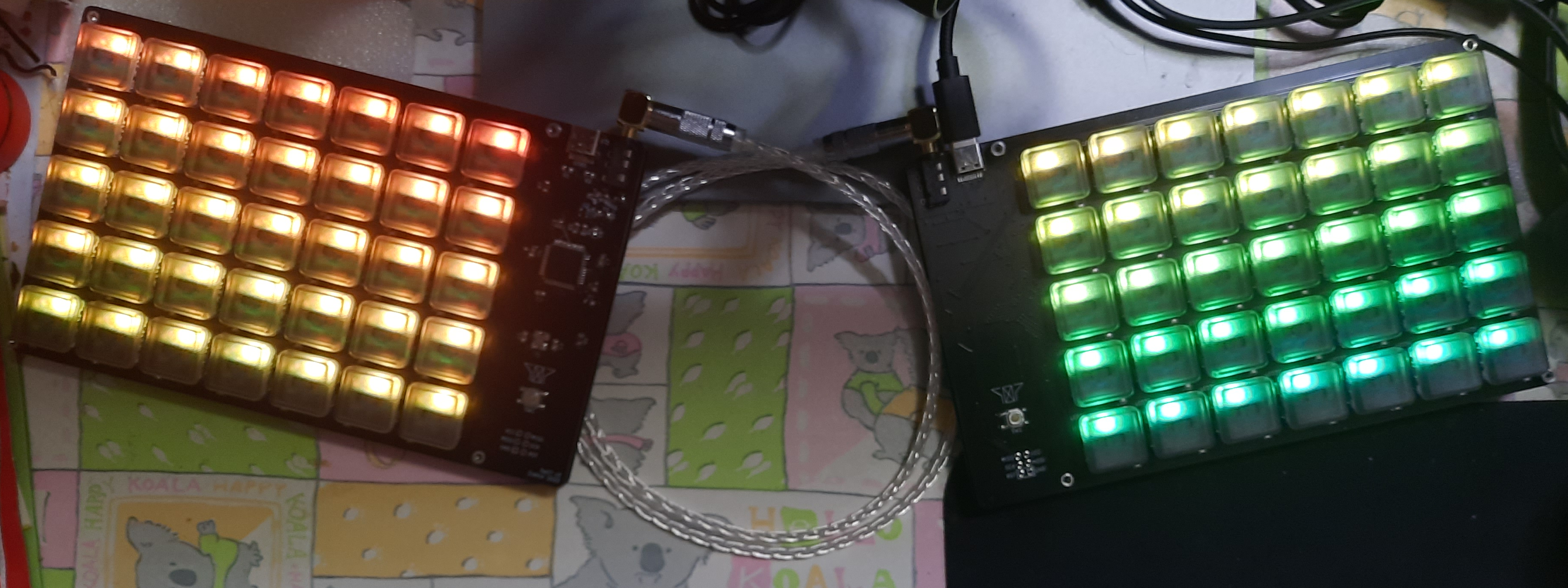
A low profile ortholinear split keyboard with per-key RGB.
5x07 is an open-source printed circuit board by Zokhoi, from the Zokhoi/5x07 repository on GitHub. It is a 2-layer board of 168.3 × 103.2 mm with 136 parts on 114 nets, routed with 1,220 tracks and 335 vias.
It is built around the ATMEGA32U4-AU and PRTR5V0U2X. Its parts include 71 diodes, 36 switches, 9 resistors, 8 capacitors and 2 ICs. It belongs with the keyboards and input and lEDs and displays boards and the AVR (ATmega, ATtiny) boards of this library.


A low profile ortholinear split keyboard with per-key RGB.
This is a project that began as my first adventure into PCB and keyboard design.
This table is for one PCB. You need double of this for both hands.
| Part | Part Details | Quantity | Notes |
|---|---|---|---|
| ATmega32u4-AU | TQFP-44 | 1 | |
| Korean Hroparts Elec TYPE-C-31-M-12 | 1 | ||
| Korean Hroparts ELEC PJ-3200B-4A TRRS Jack | 1 | For split keyboard connection | |
| SK6812 Mini-E Reverse Mount LED | 35 | ||
| 16MHz 3225 SMD Crystal | 1 | ||
| PRTR5V0U2X | SOT143B | For ESD protection | |
| SKQG push button switch | 1 | For reset circuit | |
| 0608/2012 SMD Resistor | 10kΩ | 3 | For MCU HWB and TRRS jack (i2c) |
| 500Ω | 1 | For keyboard LED | |
| 5.1kΩ | 2 | For USB-C CC | |
| 22Ω | 2 | For USB-C data | |
| 330Ω | 1 | For reset circuit | |
| 1206/3212 SMD Fuse | 500mA | 1 | |
| Diodes | 1N4148 or SMD | 35 | For keyboard matrix |
| Schottky | 1 | For USB-C power | |
| 0805 SMD Capacitors | 22 pF | 2 | For crystal |
| 1 uF | 1 | For MCU UCAP | |
| 10 uF | 1 | For decoupling | |
| 0.1 uF | 4 | For decoupling | |
| M2 screws | >=3mm | 8 | For bottom plate, length for reference only |
| M2 standoff | 3mm | 4 | For bottom plate, length for reference only |
Fabrication gerber files are in ./PCB/gerber directory.
103.188 mm H x 168.275 mm W
2 layers
Unleaded HASL or ENIG
1.6mm thick
white on black
The images below are PCBs for v3.
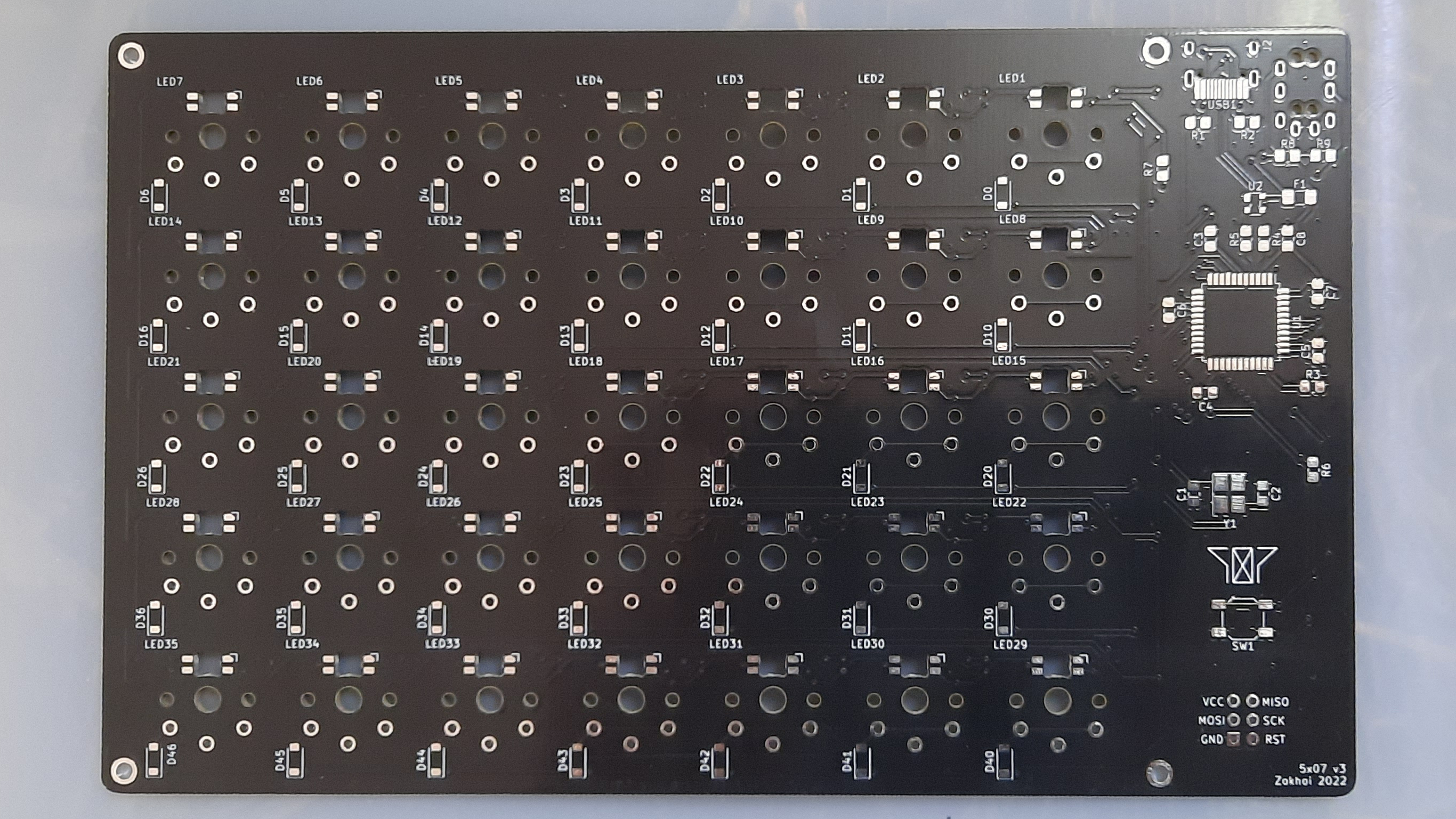
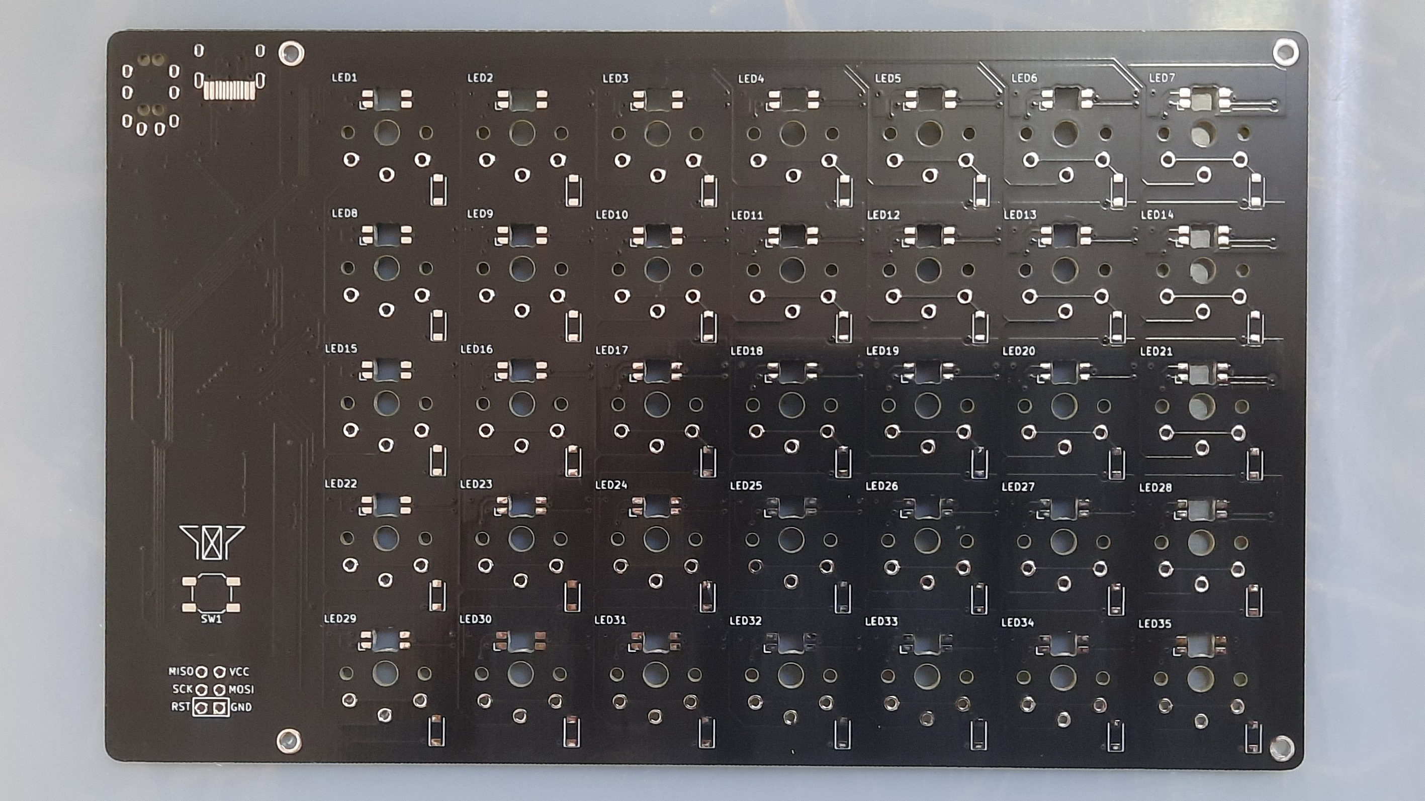
The board is designed to be reversible. You can flip the PCB to the other side to serve as the other half.
The parts that are mountable on both sides of the PCB are the type C port, the TRRS jack, the reset button and the key matrix (switch, LED, diode).
The side for mounting type C port and TRRS jack is up to your will. The reset button should always face up for ease of access. The LEDs for keyboard are reverse mounted. Key diodes should be on the underside.
As one side would have its electrionic components mostly facing down, you should lift the split halves up to avoid shorting. If you have leftover boards from ordering in batch amounts, it is possible to use them as bottom plates using M2 screws and standoffs.
For information, the shortest M2 standoffs I can find are 3mm in length, the type C port is 3.2mm high, and the TRRS jack is 5mm high (the outer plastic ring might be 5.6mm high). If you decide to put the type C port and TRRS jack on the top side, you can have the standoff as short as just higher than the electronic components on the board.
By default the keyboard is set to use EEPROM handedness check, this means that for the first time for both halves the following commands need to be used:
make 5x07:default:dfu-split-left
make 5x07:default:dfu-split-right
afterwards the end part can be dropped when flashing again.
For v3 and below there is no VBUS detection, so USB activity detection must be used for split master detection if you do not want to hardcode the master half.
V3.1 onwards has VBUS detection and you can use it normally.
I couldn't for the life of me figure out how to stably enable the per key RGB, so use at your own risk.
Some problems that I encountered were:
| Qty | Value | Footprint | References |
|---|---|---|---|
| 35 | D_Small | assets:D_SOD-123-Reversible | D0, D1, D2, D10, D11, D12, D13, D14, D15, D16, D20, D21, D22, D23, D24, D25 +19 |
| 35 | choc_SK6812MINI-E | assets:LED_choc_6028R_Reversible_same_side | LED1, LED2, LED10, LED11, LED12, LED13, LED14, LED15, LED16, LED17, LED18, LED19, LED20, LED21, LED22, LED23 +19 |
| 4 | 0.1uF | Capacitor_SMD:C_0805_2012Metric_Pad1.18x1.45mm_HandSolder | C4, C5, C6, C7 |
| 4 | MountingHole_Pad | random-keyboard-parts:Generic-Mounthole | H1, H2, H3, H4 |
| 4 | SW_Push | assets:SW_choc_1u_reversible | K10, K20, K30, K40 |
| 3 | 10k | Resistor_SMD:R_0805_2012Metric_Pad1.20x1.40mm_HandSolder | R3, R8, R9 |
| 2 | 22 | Resistor_SMD:R_0805_2012Metric_Pad1.20x1.40mm_HandSolder | R4, R5 |
| 2 | 22pF | Capacitor_SMD:C_0805_2012Metric_Pad1.18x1.45mm_HandSolder | C1, C2 |
| 2 | 5.1k | Resistor_SMD:R_0805_2012Metric_Pad1.20x1.40mm_HandSolder | R1, R2 |
| 2 | KC_SPACE | assets:SW_choc_1u_reversible | K45, K46 |
| 1 | 10uF | Capacitor_SMD:C_0805_2012Metric_Pad1.18x1.45mm_HandSolder | C8 |
| 1 | 16MHz | Crystal:Crystal_SMD_3225-4Pin_3.2x2.5mm_HandSoldering | Y1 |
| 1 | 1uF | Capacitor_SMD:C_0805_2012Metric_Pad1.18x1.45mm_HandSolder | C3 |
| 1 | 330 | Resistor_SMD:R_0805_2012Metric_Pad1.20x1.40mm_HandSolder | R6 |
| 1 | 500 | Resistor_SMD:R_0805_2012Metric_Pad1.20x1.40mm_HandSolder | R7 |
| 1 | 500mA | Fuse:Fuse_1206_3216Metric_Pad1.42x1.75mm_HandSolder | F1 |
| 1 | ATmega32U4-A | Package_QFP:TQFP-44_10x10mm_P0.8mm | U1 |
| 1 | AVR-ISP-6 | random-keyboard-parts:Reset_Pretty | J1 |
| 1 | AudioJack3_Ground | assets:PJ-3200B-4A-Reversible-Mini | J2 |
| 1 | D_Schottky | Diode_SMD:D_SOD-123F | D7 |
| 1 | HRO-TYPE-C-31-M-12 | assets:HRO-TYPE-C-31-M-12-HandSoldering-Reversible | USB1 |
| 1 | KC_1 | assets:SW_choc_1u_reversible | K2 |
| 1 | KC_2 | assets:SW_choc_1u_reversible | K3 |
| 1 | KC_3 | assets:SW_choc_1u_reversible | K4 |
| 1 | KC_4 | assets:SW_choc_1u_reversible | K5 |
| 1 | KC_5 | assets:SW_choc_1u_reversible | K6 |
| 1 | KC_A | assets:SW_choc_1u_reversible | K22 |
| 1 | KC_B | assets:SW_choc_1u_reversible | K36 |
| 1 | KC_C | assets:SW_choc_1u_reversible | K34 |
| 1 | KC_CAPS | assets:SW_choc_1u_reversible | K21 |
| 1 | KC_D | assets:SW_choc_1u_reversible | K24 |
| 1 | KC_E | assets:SW_choc_1u_reversible | K14 |
| 1 | KC_ESC | assets:SW_choc_1u_reversible | K0 |
| 1 | KC_F | assets:SW_choc_1u_reversible | K25 |
| 1 | KC_FN | assets:SW_choc_1u_reversible | K44 |
| 1 | KC_G | assets:SW_choc_1u_reversible | K26 |
| 1 | KC_GRV | assets:SW_choc_1u_reversible | K1 |
| 1 | KC_LALT | assets:SW_choc_1u_reversible | K43 |
| 1 | KC_LCTL | assets:SW_choc_1u_reversible | K41 |
| 1 | KC_LGUI | assets:SW_choc_1u_reversible | K42 |
| 1 | KC_LSFT | assets:SW_choc_1u_reversible | K31 |
| 1 | KC_Q | assets:SW_choc_1u_reversible | K12 |
| 1 | KC_R | assets:SW_choc_1u_reversible | K15 |
| 1 | KC_S | assets:SW_choc_1u_reversible | K23 |
| 1 | KC_T | assets:SW_choc_1u_reversible | K16 |
| 1 | KC_TAB | assets:SW_choc_1u_reversible | K11 |
| 1 | KC_V | assets:SW_choc_1u_reversible | K35 |
| 1 | KC_W | assets:SW_choc_1u_reversible | K13 |
| 1 | KC_X | assets:SW_choc_1u_reversible | K33 |
| 1 | KC_Z | assets:SW_choc_1u_reversible | K32 |
| 1 | PRTR5V0U2X | random-keyboard-parts:SOT143B | U2 |
| 1 | SW_Push | assets:SW_SPST_SKQG_WithStem_Reversible | SW1 |
The 135 most common of 136 parts.
sadekbaroudi/barobord
I have spent a lot of time and money designing prototypes, testing, developing, etc. Any contributions would be greatly appreciated!


markstory/ursa-minor-keyboard
Design and schematics for the ursaminor keyboard


makenova/reverie
a mini 1800 keyboard based on the Elongate, Clarabelle, and Garbage Truck Keyboards

makenova/micro_redox
A family of boards inspired by the microdox and ferris

It measures 168.3 × 103.2 mm and has 2 copper layers, 1.6 mm thick.
136 parts, built around the ATMEGA32U4-AU and PRTR5V0U2X. The full list of its parts is on this page, with links to each part's symbol and footprint where PCBKit's library has them.
From the Zokhoi/5x07 repository on GitHub, at the commit this page was made from: the board is PCB/5x07.kicad_pcb and its schematic PCB/5x07.kicad_sch. PCBKit opens the board in the browser, with nothing to install.
Its repository states no licence, so its author keeps all rights: ask Zokhoi before reusing the design.