2 layers111 × 80 mm
 ZeroPhone/Snowdive-PCB2
ZeroPhoneNext PCBs
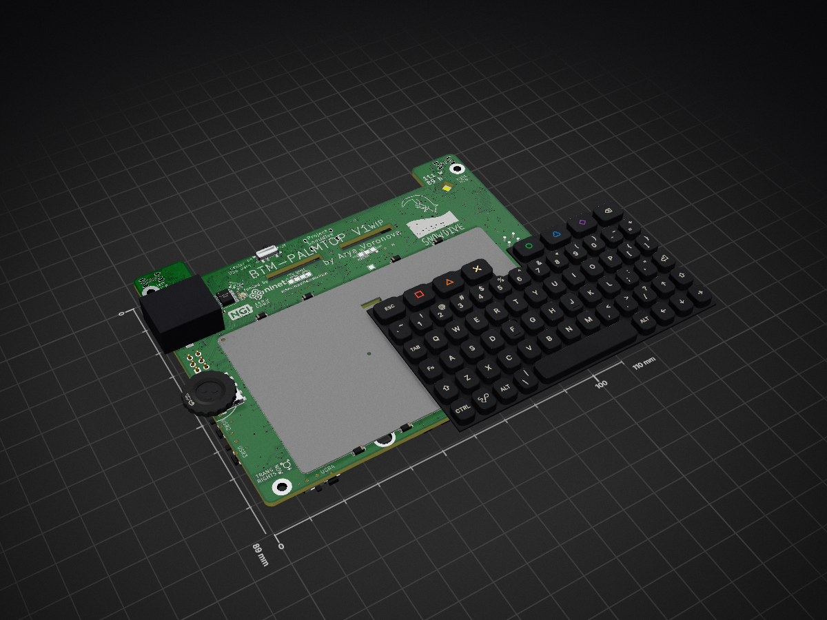
Bottom board palmtop is an open-source printed circuit board by ZeroPhone, from the ZeroPhone/Snowdive-PCB repository on GitHub, published under the CERN-OHL-S-2.0 licence. It is a 2-layer board of 110 × 89 mm with 407 parts on 320 nets, routed with 8,168 tracks and 1,139 vias.
It is built around the WUSB3801Q-12/TR, FUSB302B01MPX and TPAZ1043-04F, with the SY6280AAAC, PI3USB42ZMEX and XL9535QF24 among its other parts. Its parts include 108 resistors, 82 capacitors, 44 ICs, 39 diodes and 12 transistors.


This board is confirmed to function standalone. It also is designed (but currently untested) to function connected to a bottom board, for instance, the BTM-PALMTOP.
This board works from a 5V/1.5A or 5V/3A input. If you want to get USB host mode out of the, you can use many of the generic "USB-C with data output and charger input" docks; connect the charger first, then plug the USB-C into the board.
You can still use the Pi Zero HDMI port for setup if required for OS setup.
You might benefit from a USB-UART adapter for debugging the system, though it's not required. A USB-UART adapter can be connected into the expansion header. Remember to check config.txt and cmdline.txt to make sure that UART console is enabled.
I2C GPIO a),modem buck section (can reuse the removed R6 for this)mEN_5V_BOOST, section 5V boost,LTE modem section if it's found out to be shorting the modem VBAT +3V5 rail (possible if it was assembled incorrectly by JLCPCB, which has a likelihood of 50%).None.
Make sure to run raspi-config to enable I2C, and that i2c-dev is added into /etc/modules.
Before attempting to work with data on the USB-C port, slide the switch right next to it away from the USB-C port. This will disengage the hardware switch on the USB data pins.
By default, USB from the Pi Zero is routed directly to the USB-C socket. This allows you to use the USB gadget mode (for networking/serial/storage over USB), as well as the BCM bootloader mode (entered upon boot without an SD card inserted).
If you want to enable the onboard USB hub (including the modem USB downlink and two of the downlinks exposed to a bottom board), you have to run these console commands:
i2cset -y 1 0x24 7 0xaf; i2cset -y 1 0x24 3 0xefThe i2c-tools package is a prerequisite for this - you can get it by using sudo apt install i2c-tools.
The USB-C socket will then get connected through a USB hub, instead of being connected directly.
Note: This command can also be executed when using a network connection over USB (i.e. USB-Ethernet), but do expect that you might need to open a new SSH session, as the old session might freeze.
Next revision will join these pins into a single GPIO, so the command for V1 will change.
To power up the modem +3V5 power rail, issue this command:
i2cset -y 1 0x25 7 0xefThe i2c-tools package is a prerequisite for this - you can get it by using sudo apt install i2c-tools.
| Qty | Value | Footprint | References |
|---|---|---|---|
| 44 | 100nF | Capacitor_SMD:C_0402_1005Metric | C1, C2, C13, C14, C15, C16, C17, C19, C20, C23, C24, C25, C26, C27, C28, C29 +28 |
| 27 | 51K | Resistor_SMD:R_0402_1005Metric | R2, R30, R32, R34, R36, R40, R43, R44, R53, R58, R59, R100, R101, R106, R112, R116 +11 |
| 24 | TPAZ1043-04F | Package_SON:USON-10_2.5x1.0mm_P0.5mm | U1, U2, U10, U11, U12, U13, U14, U15, U16, U17, U18, U19, U20, U22, U23, U26 +8 |
| 17 | 1uF | Capacitor_SMD:C_0402_1005Metric | C3, C8, C10, C18, C21, C22, C31, C45, C46, C55, C56, C57, C60, C69, C81, C82 +1 |
| 15 | 27R | Resistor_SMD:R_0402_1005Metric | R1, R14, R18, R20, R21, R52, R62, R63, R65, R95, R108, R109, R110, R111, R115 |
| 14 | 10K | Resistor_SMD:R_0402_1005Metric | R10, R19, R29, R31, R54, R68, R72, R74, R75, R76, R79, R82, R94, R107 |
| 14 | 2K | Resistor_SMD:R_0402_1005Metric | R11, R12, R13, R16, R28, R42, R48, R61, R64, R86, R87, R92, R102, R103 |
| 14 | D_Schottky_Small | Diode_SMD:D_SOD-323 | D1, D2, D3, D4, D5, D10, D16, D18, D19, D21, D22, D23, D24, D26 |
| 12 | 5.1K | Resistor_SMD:R_0402_1005Metric | R15, R17, R23, R24, R25, R38, R41, R51, R57, R84, R85, R90 |
| 12 | KBLED | bottom_board_palmtop:LTW-010DCG | D6, D7, D8, D9, D11, D12, D13, D14, D27, D28, D29, D30 |
| 9 | 270R | Resistor_SMD:R_0402_1005Metric | R3, R4, R5, R6, R7, R8, R9, R56, R93 |
| 8 | 2N7002DW-7-F | Package_TO_SOT_SMD:SOT-363_SC-70-6 | Q1, Q2, Q4, Q7, Q8, Q14, Q18, Q19 |
| 6 | 10uF | Capacitor_SMD:C_0805_2012Metric_Pad1.18x1.45mm_HandSolder | C39, C40, C51, C54, C58, C59 |
| 6 | GND | bottom_board_palmtop:TestPoint_Pad_0.6x0.6mm | TP13, TP23, TP24, TP25, TP26, TP48 |
| 6 | SY6280AAAC | Package_TO_SOT_SMD:SOT-23-5 | U24, U25, U30, U31, U46, U53 |
| 5 | 22uF | Capacitor_SMD:C_0805_2012Metric_Pad1.18x1.45mm_HandSolder | C32, C33, C34, C41, C44 |
| 5 | EVQPUL02K | Button_Switch_SMD:Panasonic_EVQPUL_EVQPUC | SW7, SW8, SW9, SW11, SW12 |
| 5 | ON/OFF | bottom_board_palmtop:SW_SPDT_PCM12_SH | SW2, SW4, SW5, SW6, SW10 |
| 5 | PI3USB42ZMEX | bottom_board_palmtop:QFN40P140X180X55-10N | U32, U35, U39, U49, U50 |
| 4 | 10uF | Capacitor_SMD:C_0402_1005Metric | C52, C53, C67, C68 |
| 4 | 1K | Resistor_SMD:R_0402_1005Metric | R22, R26, R27, R105 |
| 4 | 240K | Resistor_SMD:R_0402_1005Metric | R35, R37, R46, R73 |
| 4 | 2A PTC | Fuse:Fuse_1206_3216Metric | F1, F2, F3, F4 |
| 4 | Battery | bottom_board_palmtop:JST_PH_B2B-PH-SM4-TB_1x02-1MP_P2.00mm_Vertical | J7, J8, J9, J10 |
| 4 | CJ2305 | Package_TO_SOT_SMD:SOT-23 | Q3, Q5, Q6, Q9 |
| 4 | LED 0603 Orange | LED_SMD:LED_0603_1608Metric | LED1, LED3, LED4, LED5 |
| 4 | MH | MountingHole:MountingHole_2.5mm_Pad | H1, H2, H3, H4 |
| 3 | 22K | Resistor_SMD:R_0402_1005Metric | R71, R89, R91 |
| 3 | LED 0603 | LED_SMD:LED_0603_1608Metric | LED8, LED10, LED11 |
| 3 | SH 4P | Connector_JST:JST_SH_SM04B-SRSS-TB_1x04-1MP_P1.00mm_Horizontal | J6, J12, J50 |
| 3 | SS34 | Diode_SMD:D_SMA | D15, D17, D31 |
| 2 | 100pF | Resistor_SMD:R_0402_1005Metric | R33, R55 |
| 2 | 10uF/20V | Capacitor_SMD:C_0805_2012Metric_Pad1.18x1.45mm_HandSolder | C36, C37 |
| 2 | 12MHz | Crystal:Crystal_SMD_3225-4Pin_3.2x2.5mm | Y1, Y2 |
| 2 | 12pF | Capacitor_SMD:C_0402_1005Metric | C11, C12 |
| 2 | GND | TestPoint:TestPoint_Pad_1.5x1.5mm | TP42, TP51 |
| 2 | LED 0603 Green | LED_SMD:LED_0603_1608Metric | Green1, Green2 |
| 2 | LQH5BPN 1R0 | bottom_board_palmtop:L_Murata_LQH5BPN | L3, L4 |
| 2 | MH | bottom_board_palmtop:MountingHole_2.5mm_Pad-paste | H5, H6 |
| 2 | NP | Resistor_SMD:R_0603_1608Metric | R47, R50 |
| 2 | SH 2P | Connector_JST:JST_SH_BM02B-SRSS-TB_1x02-1MP_P1.00mm_Vertical | J45, J54 |
| 2 | SK6812MINI-EA | bottom_board_palmtop:LED-SMD_4P-L3.2-W2.8_SK6812MINI-EA | LED6, LED7 |
| 2 | VBR+ | TestPoint:TestPoint_Pad_1.0x1.0mm | TP1, TP22 |
| 2 | VBR- | TestPoint:TestPoint_Pad_1.0x1.0mm | TP2, TP21 |
| 2 | WUSB3801Q-12/TR | bottom_board_palmtop:X2QFN-12_L1.6-W1.6-P0.40-LS1.2 | U27, U29 |
| 2 | XL9535QF24 | Package_DFN_QFN:QFN-24-1EP_4x4mm_P0.5mm_EP2.5x2.5mm | U21, U28 |
| 1 | 0R | Resistor_SMD:R_0402_1005Metric | R45 |
| 1 | 1uF | Capacitor_SMD:C_0805_2012Metric_Pad1.18x1.45mm_HandSolder | C80 |
| 1 | 33K | Resistor_SMD:R_0402_1005Metric | R39 |
| 1 | 3V3 | TestPoint:TestPoint_Pad_1.5x1.5mm | TP39 |
| 1 | 3V3_EC | bottom_board_palmtop:TestPoint_Pad_0.6x0.6mm | TP14 |
| 1 | 47nF | Capacitor_SMD:C_0402_1005Metric | C65 |
| 1 | 5V1 | Diode_SMD:D_0805_2012Metric | D20 |
| 1 | ADDON_ONLY | bottom_board_palmtop:SolderJumper-2_smol_Open | JP3 |
| 1 | AP2114 | Package_TO_SOT_SMD:SOT-223-3_TabPin2 | U48 |
| 1 | AP62600SJ-7 | bottom_board_palmtop:QFN-12_L3.0-W2.0-P0.50-TL_AP62600SJ-7 | U36 |
| 1 | BL24C32A | Package_DFN_QFN:DFN-8-1EP_3x2mm_P0.5mm_EP1.3x1.5mm | U40 |
| 1 | BOOTSEL_JUMPER | Jumper:SolderJumper-2_P1.3mm_Bridged_RoundedPad1.0x1.5mm | JP2 |
| 1 | BZ_V | Jumper:SolderJumper-3_P1.3mm_Bridged12_RoundedPad1.0x1.5mm | JP6 |
| 1 | CH334P | Package_DFN_QFN:QFN-16-1EP_3x3mm_P0.5mm_EP1.7x1.7mm | U47 |
| 1 | CPU_SCL | bottom_board_palmtop:TestPoint_Pad_0.6x0.6mm | TP16 |
| 1 | CPU_SDA | bottom_board_palmtop:TestPoint_Pad_0.6x0.6mm | TP17 |
| 1 | Center USB | Connector_USB:USB_C_Receptacle_HRO_TYPE-C-31-M-12 | J3 |
| 1 | EA | TestPoint:TestPoint_Pad_1.5x1.5mm | TP50 |
| 1 | EB | TestPoint:TestPoint_Pad_1.5x1.5mm | TP49 |
| 1 | EC-A_INT | bottom_board_palmtop:TestPoint_Pad_0.6x0.6mm | TP27 |
| 1 | EC-B_INT | bottom_board_palmtop:TestPoint_Pad_0.6x0.6mm | TP28 |
| 1 | EC_INT | bottom_board_palmtop:TestPoint_Pad_0.6x0.6mm | TP15 |
| 1 | EC_PRESENT | bottom_board_palmtop:TestPoint_Pad_0.6x0.6mm | TP20 |
| 1 | EC_SCL | bottom_board_palmtop:TestPoint_Pad_0.6x0.6mm | TP19 |
| 1 | EC_SDA | bottom_board_palmtop:TestPoint_Pad_0.6x0.6mm | TP18 |
| 1 | FDSD0518 1uH | bottom_board_palmtop:L_Murata_FDSD0518 | L1 |
| 1 | FFC_1 | bottom_board_palmtop:FPC-SMD_30P-P0.50_XF3M-3015-1B | J5 |
| 1 | FFC_1_D+ | bottom_board_palmtop:TestPoint_Pad_0.6x0.6mm | TP11 |
| 1 | FFC_1_D- | bottom_board_palmtop:TestPoint_Pad_0.6x0.6mm | TP12 |
| 1 | FFC_2 | bottom_board_palmtop:FPC-SMD_30P-P0.50_XF3M-3015-1B | J4 |
| 1 | FFC_2_D+ | bottom_board_palmtop:TestPoint_Pad_0.6x0.6mm | TP10 |
| 1 | FFC_2_D- | bottom_board_palmtop:TestPoint_Pad_0.6x0.6mm | TP9 |
| 1 | FST-5020 | bottom_board_palmtop:BUZ-SMD_FST-5020 | BUZZER1 |
| 1 | FUSB302B01MPX | Package_DFN_QFN:WQFN-14-1EP_2.5x2.5mm_P0.5mm_EP1.45x1.45mm | U33 |
The 356 most common of 407 parts.

CRImier/MyKiCad
My KiCad boards. Can't be bothered uploading individually anymore, so here you go.

American-Embedded/isolated_reindvstrialize_usb_hub
This repository contains a KiCad project template provided by American Embedded. It is designed to be a starting point for new electronic designs, pre-configured with common settings, layers, and manufacturing outputs.


makeTVee/MYNDlights
Adding lights to a Teufel Mynd bluetooth speaker


It measures 110 × 89 mm and has 2 copper layers, 1.6 mm thick.
407 parts, built around the WUSB3801Q-12/TR, FUSB302B01MPX, TPAZ1043-04F and SY6280AAAC. The full list of its parts is on this page, with links to each part's symbol and footprint where PCBKit's library has them.
From the ZeroPhone/Snowdive-PCB repository on GitHub, at the commit this page was made from: the board is bottom_board_palmtop/bottom_board_palmtop.kicad_pcb and its schematic bottom_board_palmtop/battery.kicad_sch. PCBKit opens the board in the browser, with nothing to install.
Its repository publishes it under the CERN-OHL-S-2.0 licence: you may reuse it on that licence's terms (keep the author's notice, and for a copyleft licence share your changes alike).