
4 layers126.6 × 37.7 mm
Gruzik2.0
NYDEREK/LineFollower_GRUZIK2.0-light
GRUZIK2.0 is simple light construction made for "line follower light" competition
50 parts101MIT

 ZIZO932/Line-follower-Bot2
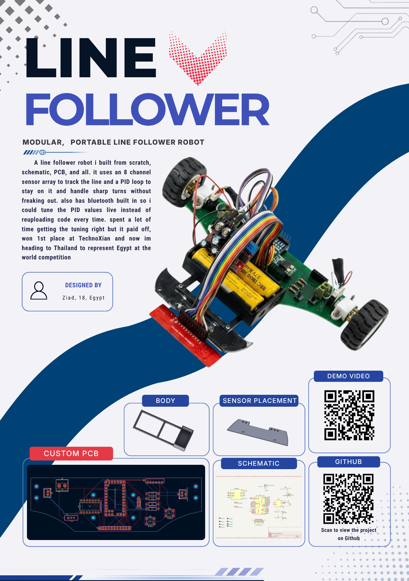
A line follower robot i built from scratch, schematic, PCB, and all. it uses an 8 channel sensor array to track the line and a PID loop to stay on it and handle sharp turns without freaking out. also has bluetooth built in so i could tune the PID values live instead of reuploading code every time.
Line follower Fallout is an open-source printed circuit board by ZIZO932, from the ZIZO932/Line-follower-Bot repository on GitHub. It is a 2-layer board of 150 × 47 mm with 23 parts on 44 nets, routed with 162 tracks and 0 vias.
It is built around the HC-05. Its parts include 4 resistors, 3 connectors, 2 ICs and 1 switch.
This is my competition line follower. Our team won first place in the seniors line follower category at TechnoXian Egypt and qualified for the World Cup in Malaysia. I worked on the custom PCB, mechanical design, assembly, and tuning.
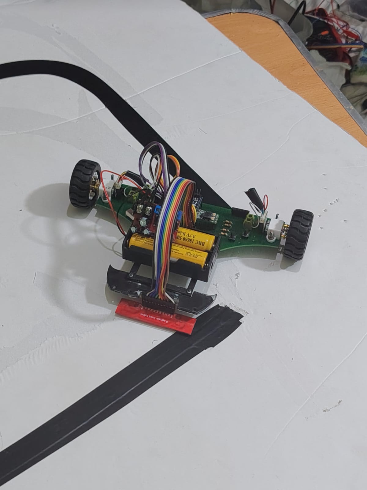
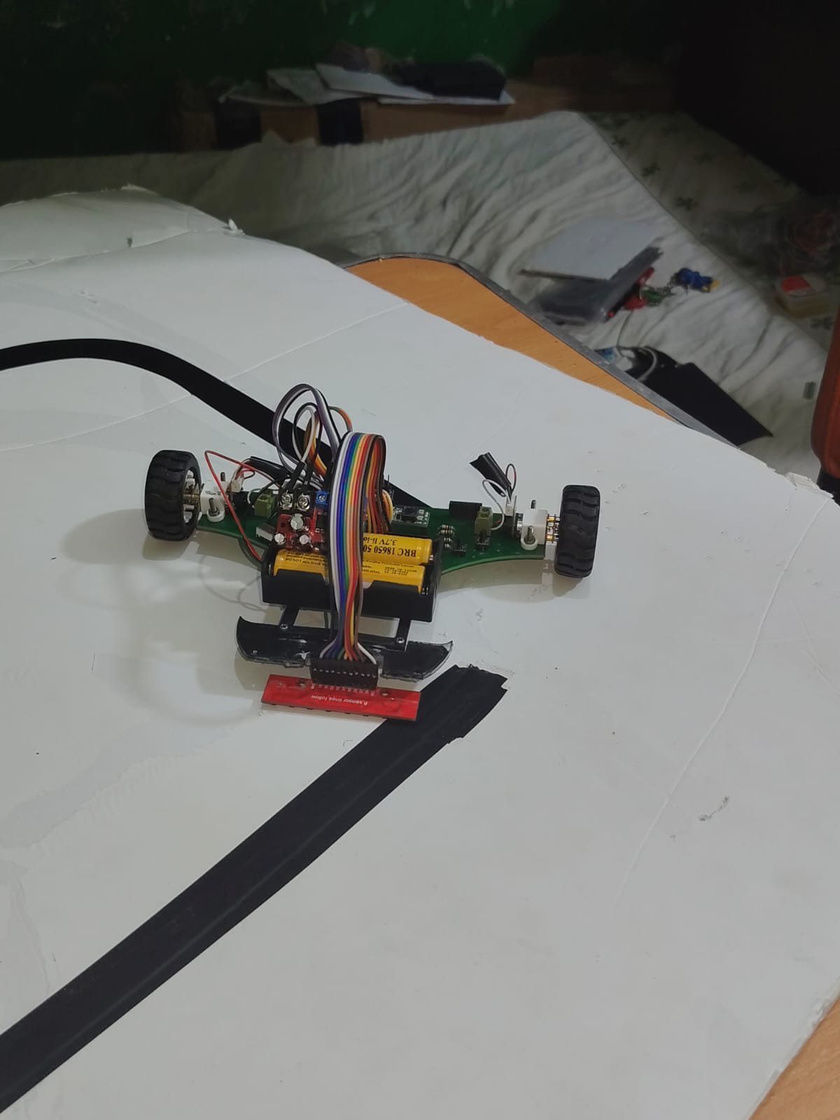
I wanted to understand PID control properly, so I researched existing line followers and built my own version around an Arduino Pro Mini and a QTR-8RC sensor array.
The robot uses the sensor array to read the line and adjust the two motors. I also added an HC-05 Bluetooth module so I could change tuning values without uploading the code again every time.
The original parts list names a DRV8835, but its supplier link points to a DRV8833. Check the circuit files and the board you're using before treating that link as an exact replacement.
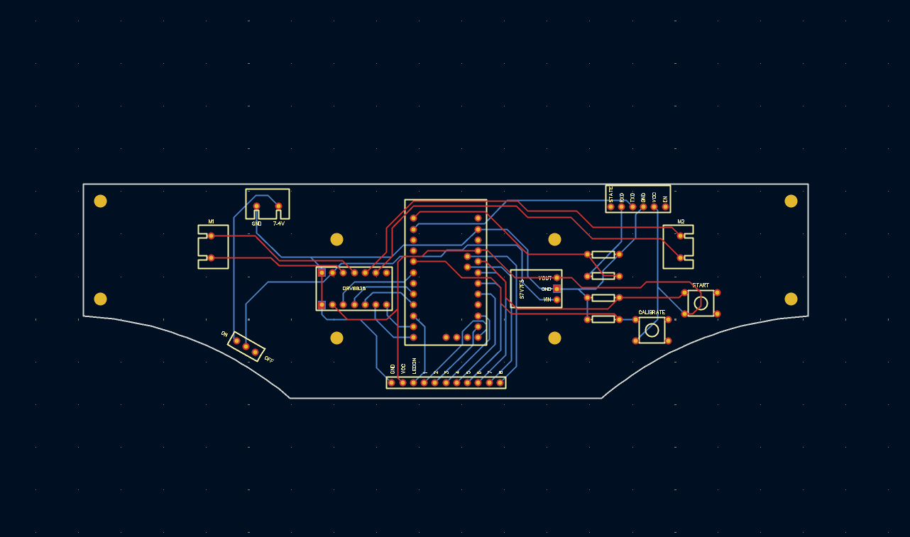
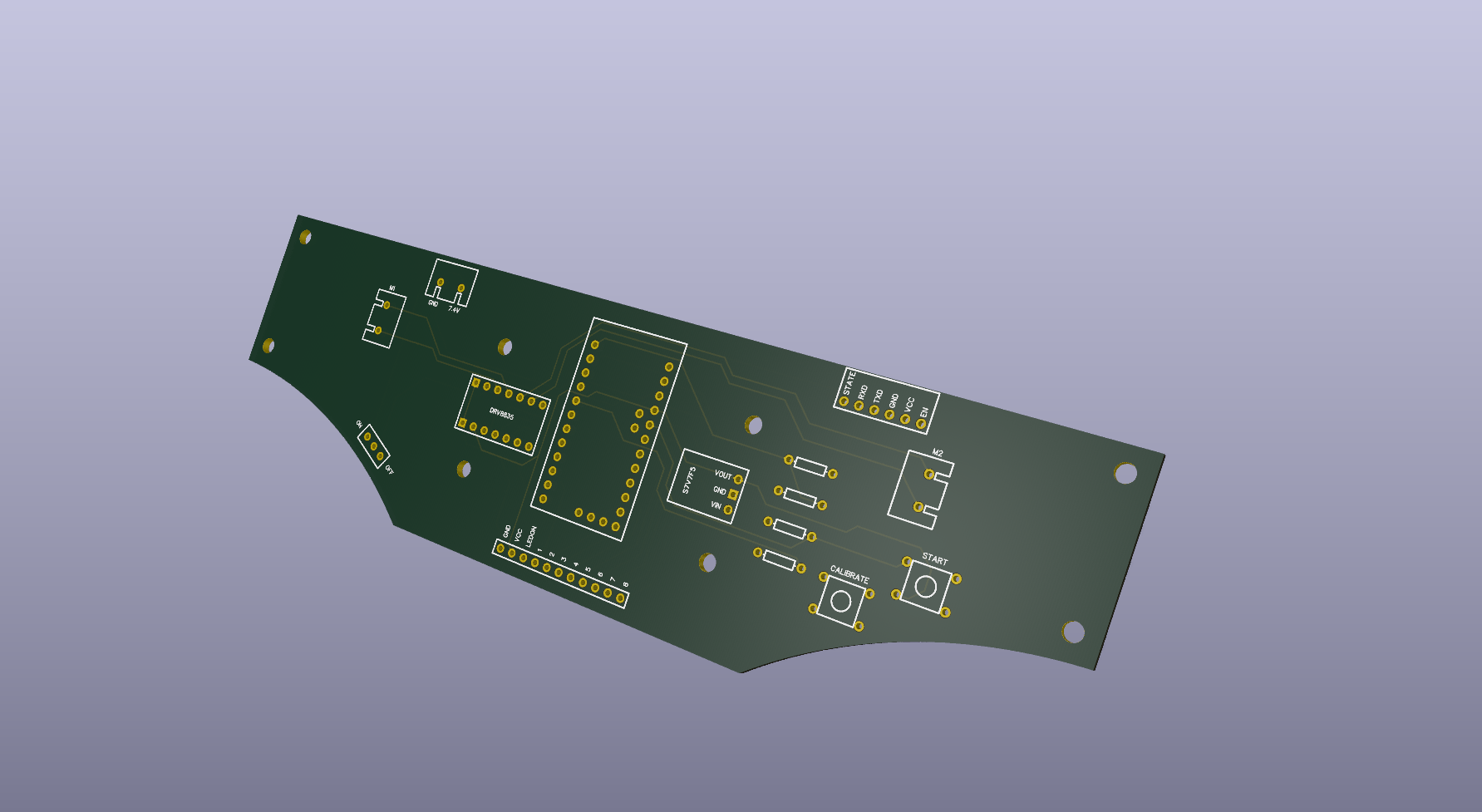
I started with the schematic, then moved to the PCB. There were footprint issues to fix before routing, and I added mounting holes so the board could screw into the body.
I designed the chassis around the electronics, keeping the sensor low and aligned with the ground and giving the battery its own support. Before the PCB arrived, I tested the controller, Bluetooth connection, motor directions, sensor channels, and regulator on a breadboard. That caught some wiring mistakes early.
Once the board arrived, I soldered it, checked for bridges and wrong orientations, and checked power and ground with a multimeter before powering it up.
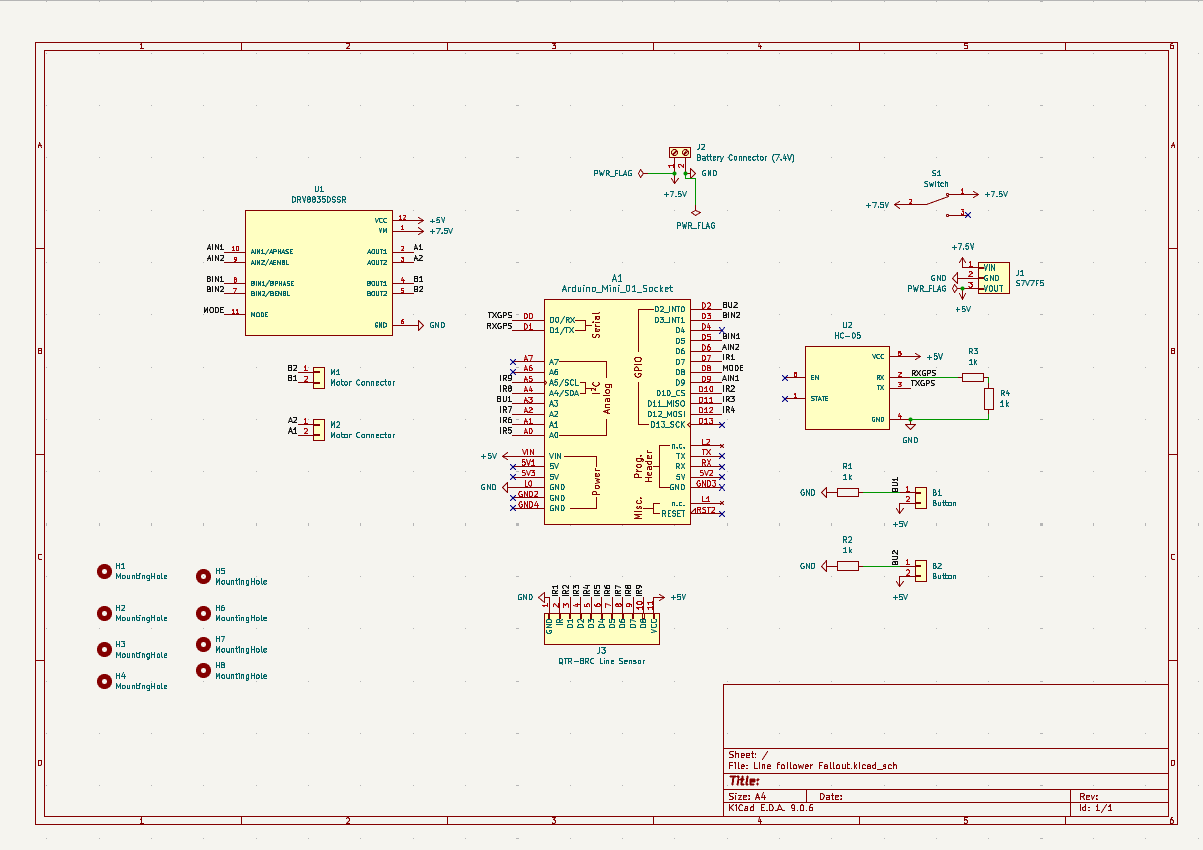
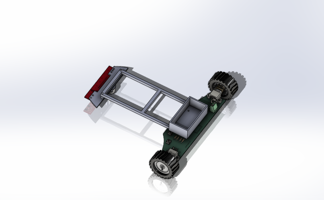
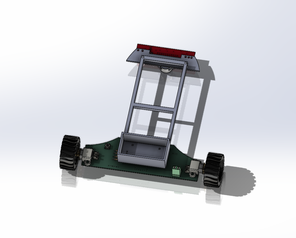
The values recorded in my build notes were Kp = 0.02, Ki = 0, and Kd = 0.6. Those belong to this setup and aren't universal settings for another robot.
Watch the S-shaped track demo or open the uploaded video.
The sketch currently uploaded in Firmware/ is a motor direction test. Despite its filename, it isn't the full PID or Bluetooth tuning firmware.
These are the original component estimates and supplier links. They aren't current prices or a complete cost for the whole robot.
I'm also planning a new standalone ATmega328P design: Line-E.
Made by Ziad, or Zizo if you know me from Hack Club.
| Qty | Value | Footprint | References |
|---|---|---|---|
| 8 | MountingHole | MountingHole:MountingHole_2.2mm_M2_DIN965 | H1, H2, H3, H4, H5, H6, H7, H8 |
| 4 | 1k | Resistor_THT:R_Axial_DIN0207_L6.3mm_D2.5mm_P10.16mm_Horizontal | R1, R2, R3, R4 |
| 2 | Button | Button_Switch_THT:SW_PUSH_6mm_H4.3mm | B1, B2 |
| 2 | Motor Connector | Connector_JST:JST_XH_B2B-XH-A_1x02_P2.50mm_Vertical | M1, M2 |
| 1 | Arduino_Mini_01_Socket | PCM_arduino-library:Arduino_Mini_Socket | A1 |
| 1 | Battery Connector (7.4V) | TerminalBlock_Phoenix:TerminalBlock_Phoenix_MKDS-1,5-2-5.08_1x02_P5.08mm_Horizontal | J2 |
| 1 | DRV8835DSSR | Package_DIP:DIP-14_W10.16mm | U1 |
| 1 | HC-05 | ZC142200:MODULE_ZC142200 | U2 |
| 1 | QTR-8RC Line Sensor | Connector_PinHeader_2.54mm:PinHeader_1x11_P2.54mm_Vertical | J3 |
| 1 | S7V7F5 | Connector_PinHeader_2.54mm:PinHeader_1x03_P2.54mm_Vertical | J1 |
| 1 | Switch | MINI-SPDT-SW:SW_MINI-SPDT-SW | S1 |
NYDEREK/LineFollower_GRUZIK2.0-light
GRUZIK2.0 is simple light construction made for "line follower light" competition


duongngochoan/Self_balancing_robot_PID
Used a PID control algorithm and MPU605 sensor to balance a two-wheeled robot.

leikoilja/muscle-imbalance-detection
A device to assist patients with the rehabilitation of the knee joint after a knee surgery using EMG biofeedback. The device can reliably detect muscle activity and display it in an easy-to-use mobile application.

xtarke/automated_buggy
This shield connects microcontroller (MSP-EXP430FR2355) pins to the car's power board. Go to Power Board for more hardware information.


It measures 150 × 47 mm and has 2 copper layers, 1.6 mm thick.
23 parts, built around the HC-05. The full list of its parts is on this page, with links to each part's symbol and footprint where PCBKit's library has them.
From the ZIZO932/Line-follower-Bot repository on GitHub, at the commit this page was made from: the board is Schematic and PCB/Line follower Fallout.kicad_pcb and its schematic Schematic and PCB/Line follower Fallout.kicad_sch. PCBKit opens the board in the browser, with nothing to install.
Its repository states no licence, so its author keeps all rights: ask ZIZO932 before reusing the design.