2 layers74 × 54 mm

 X-Lemon-X/Pilot_6_axis2
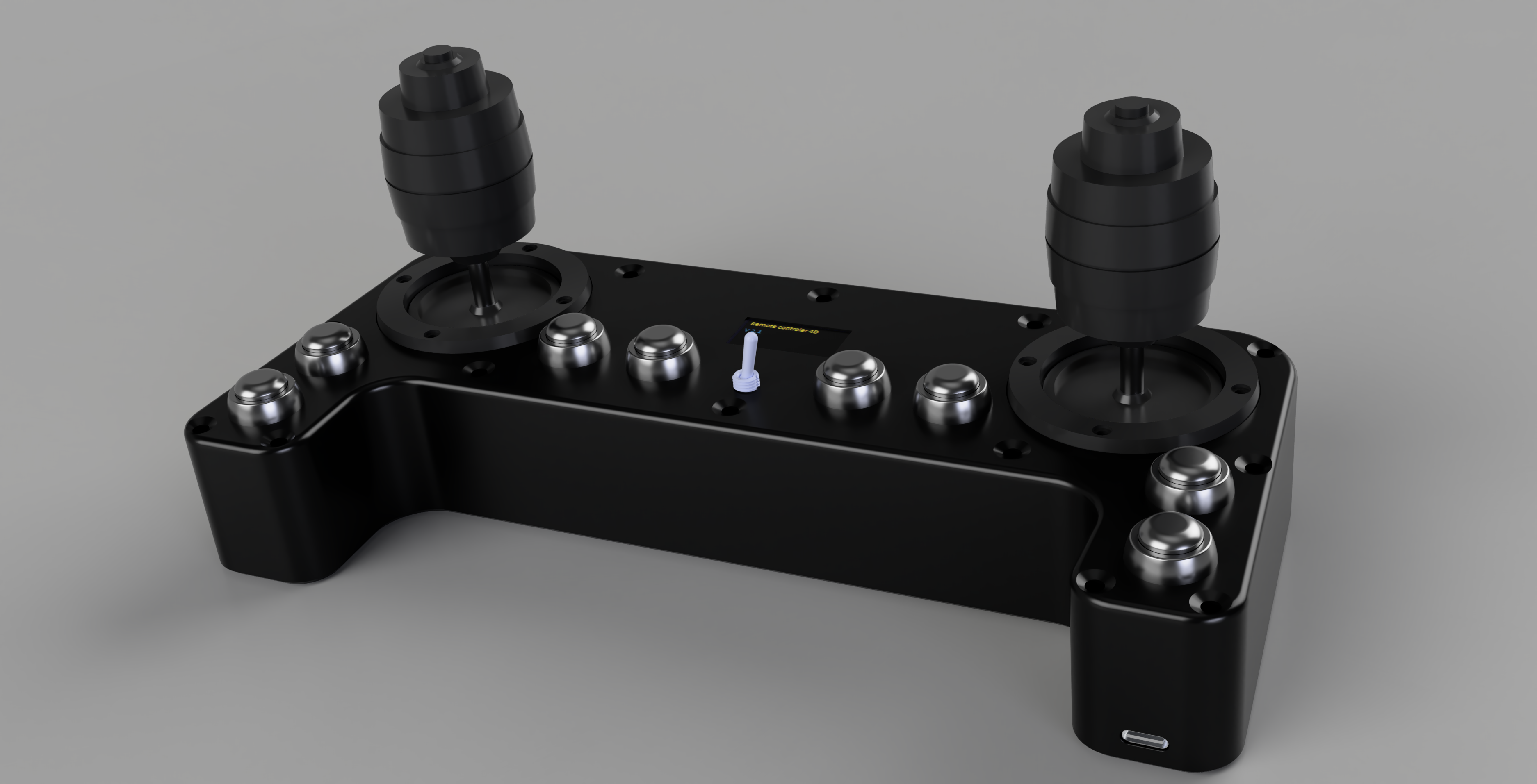
DIY Remote Controler Build
Pilot6Axis v2 is an open-source printed circuit board by X-Lemon-X, from the X-Lemon-X/Pilot_6_axis repository on GitHub, published under the MIT licence. It is a 2-layer board of 171 × 83.9 mm with 126 parts on 167 nets, routed with 846 tracks and 804 vias.
It is built around the ESP32-WROOM-32U, AMS1117-3.3 and BQ25792RQMR, with the CAT24C512WI-GT3, SN74LVC1G74RSE2 and TPS25751SRSMR among its other parts. Its parts include 47 capacitors, 32 resistors, 23 ICs, 8 diodes and 7 connectors. It belongs with the ESP32 boards of this library.


 {width=50%}
C++ implementation for reliable remote control integration. Receives UDP packets over Wi-Fi, parses 6-axis joystick and 10-button data, applies deadband filtering, and publishes to the /joy ROS 2 topic. Handles graceful disconnects by sending a zero frame when the pilot loses connection.
Python-based UDP receiver that converts remote control packets into ROS 2 sensor_msgs::msg::Joy messages for joystick control. No longer maintained; use remote_6d instead.
Pc keyboard version for RC without the need for the hardware if you want to test it or forgot to bring the RC with you :).
 python3 -m venv .venv
 python3 -m pip -r requirements.txt
 source .venv/bin/activate
python3 keyboard_rc.py -i IP_ADDRESS -p PORT -f FREQUENCY -v JOYSTICK_VALUE python3 keyboard_rc.py -i 127.0.0.1 python3 keyboard_rc.pyEnable setup mode by pressing and holding the most centeral button 4 or 5 when turning the Rc On (doesn't matter which one).
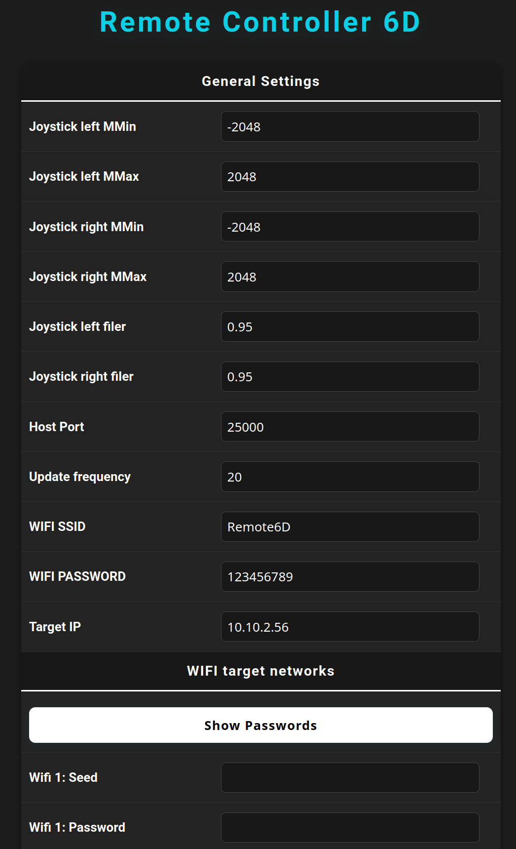
Connect to the Rc Wi-Fi network that is displayed on the LCD.
Open web browser and go to url displayed on the LCD.
Set up the settings of the Rc and press save buttons on the bottom of the page. This will redirect you to the page where you will see if settings were saved. If you made some error it will be shown here.
 {width=40%}
To leave setup mode shut down the Rc and turn it on again.
Now the Rc will connect to the network with the highest priority that is available. If it can't connect to any of the saved networks it will keep trying to connect to them. If the Rc is connected to the network it will display the IP address on the LCD and show Connected status.
Now setup is done and you can use the Rc.
colcon build --symlink-install ros2 run remote_6d remote_6d_node/joy topic.| Component | Photo | Component | Photo |
|---|---|---|---|
| PCB (order from JLCPCB) | 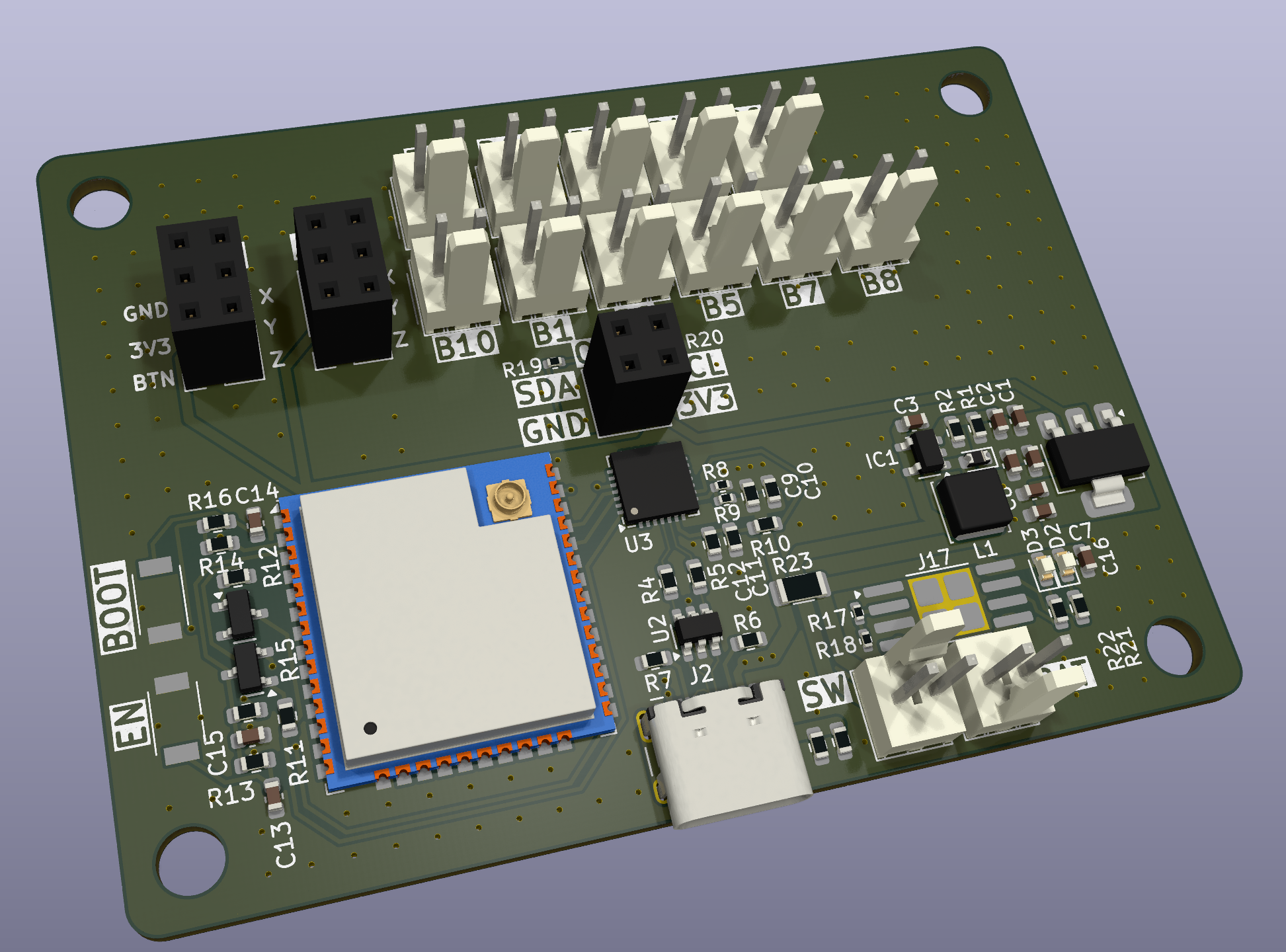 | Joystick 4-axis JH-D400B-M4 | 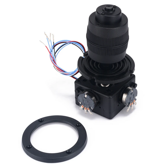 |
| Toggle switch 6mm MTS-103 | 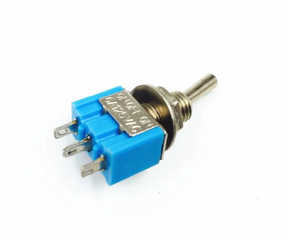 | Monostable switches 12mm PBS-33B | 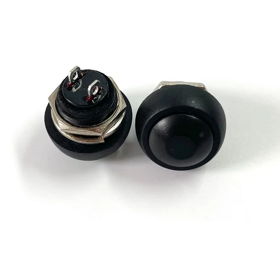 |
| Li-ion battery 3.7V 4000mAh | 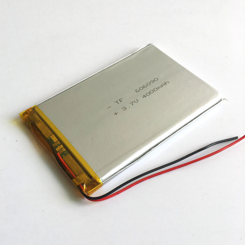 | LCD 1.3" 128x64 OLED SSD1306 | 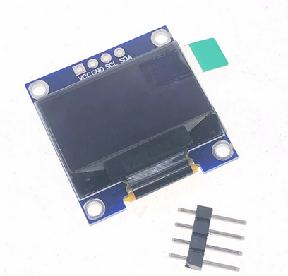 |
| Antena 2.4GHz 3dBi WiFi RP-SMA | 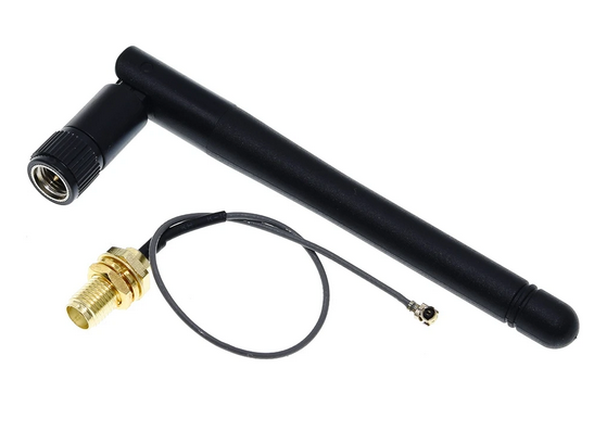 | M3 6mm hex socket flat countersunk | 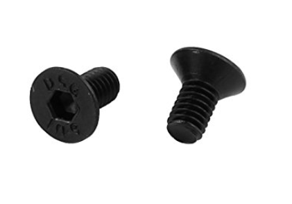 |
| M3 heated insert M3xL3xOD4.2 | 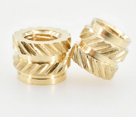 | M3 5mm hex socket cylindrical | 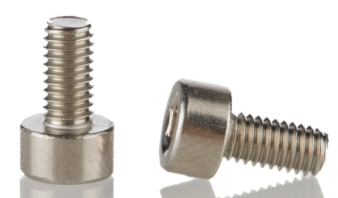 |
| Component Name | Parts Count | Description |
|---|---|---|
| Joystick 4-axis JH-D400B-M4 | 2 | 3-DOF joysticks for axis control |
| Toggle switch 6mm MTS-103 | 1 | Main toggle switch for power or mode selection |
| Monostable switches 12mm PBS-33B | 8 | Momentary push buttons for user input |
| Li-ion battery 606090 3.7V 4000mAh | 1 | Rechargeable battery for power supply |
| LCD 1.3" 128x64 OLED SSD1306 | 1 | Display for status and configuration |
| Antena 2.4GHz 3dB WiFi 2.4GHz RP-SMA | 1 | External Wi-Fi antenna for wireless communication |
| M3 6mm hex socket flat countersunk screws | 14 | Screws for assembling the enclosure |
| M3 heated insert M3xL3xOD4.2 | 19 | Threaded inserts for secure screw mounting |
| M3 5mm hex socket cylindrical screws | 4 | Additional screws for assembly |
| PCB (order from JLCPCB) | 1 | Main circuit board for the controller |
| BOM Components (see BOM file) | - | All other electronic components (resistors, ICs, etc.) |
You figure it out.
| Qty | Value | Footprint | References |
|---|---|---|---|
| 14 | 10uF | PCM_JLCPCB:C_0603 | C2, C15, C20, C21, C29, C30, C31, C32, C33, C37, C38, C40, C41, C42 |
| 11 | ~ | ts-1212f:ts-1212f | U5, U6, U7, U8, U9, U10, U11, U12, U13, U15, U16 |
| 8 | 100nF | PCM_JLCPCB:C_0603 | C17, C18, C19, C22, C25, C26, C34, C43 |
| 7 | 1kΩ | PCM_JLCPCB:R_0603 | R13, R14, R25, R28, R30, R31, R32 |
| 7 | Red | PCM_JLCPCB:D_0603 | D2, D3, D4, D5, D6, D7, D8 |
| 5 | 13.3k | Resistor_SMD:R_0603_1608Metric | R3, R11, R12, R15, R16 |
| 5 | 1nF | Capacitor_SMD:C_0603_1608Metric | C5, C6, C13, C14, C47 |
| 3 | 100n | Resistor_SMD:R_0603_1608Metric | C10, C11, C45 |
| 3 | 100nF | Capacitor_SMD:C_0603_1608Metric | C3, C7, C46 |
| 3 | 220pF | Capacitor_SMD:C_0603_1608Metric | C4, C23, C24 |
| 3 | Conn_01x06 | Connector_JST:JST_PH_B6B-PH-K_1x06_P2.00mm_Vertical | J4, J9, J10 |
| 2 | 100kΩ | PCM_JLCPCB:R_0603 | R1, R24 |
| 2 | 1nF | PCM_JLCPCB:C_0603 | C35, C36 |
| 2 | 22R | Resistor_SMD:R_0603_1608Metric | R6, R7 |
| 2 | 4.7kΩ | PCM_JLCPCB:R_0603 | R19, R20 |
| 2 | 4.7u | Resistor_SMD:R_0603_1608Metric | C9, C44 |
| 2 | 4.7uF | PCM_JLCPCB:C_0603 | C16, C39 |
| 2 | 47nF | PCM_JLCPCB:C_0603 | C27, C28 |
| 2 | 4k7 | Resistor_SMD:R_0402_1005Metric | R17, R18 |
| 2 | AO3400A | PCM_JLCPCB:Q_SOT-23 | Q3, Q4 |
| 2 | S9014 | PCM_JLCPCB:Q_SOT-23 | Q1, Q2 |
| 1 | 100Ω | PCM_JLCPCB:R_0603 | R26 |
| 1 | 10k | Connector_PinHeader_2.54mm:PinHeader_1x02_P2.54mm_Vertical | TH1 |
| 1 | 10nF | Resistor_SMD:R_0603_1608Metric | C8 |
| 1 | 10u | Resistor_SMD:R_0603_1608Metric | C12 |
| 1 | 10uH | Inductor_SMD:L_Cenker_CKCS4018 | L1 |
| 1 | 127k | Resistor_SMD:R_0603_1608Metric | R23 |
| 1 | 1k | Resistor_SMD:R_0603_1608Metric | R10 |
| 1 | 1u | Inductor_SMD:L_APV_APH0420 | L2 |
| 1 | 22k | Resistor_SMD:R_0402_1005Metric | R8 |
| 1 | 22Ω | PCM_JLCPCB:R_0603 | R29 |
| 1 | 30kΩ | PCM_JLCPCB:R_0603 | R22 |
| 1 | 330Ω | PCM_JLCPCB:R_0603 | R4 |
| 1 | 33k | Resistor_SMD:R_0603_1608Metric | R5 |
| 1 | 3kΩ | PCM_JLCPCB:R_0603 | R27 |
| 1 | 4.7uF | Capacitor_SMD:C_0603_1608Metric | C1 |
| 1 | 40.5k | Resistor_SMD:R_0603_1608Metric | R2 |
| 1 | 43k | Resistor_SMD:R_0402_1005Metric | R9 |
| 1 | 5.1kΩ | PCM_JLCPCB:R_0402 | R21 |
| 1 | AMS1117-3.3 | Package_TO_SOT_SMD:SOT-223-3_TabPin2 | U1 |
| 1 | BQ25792RQMR | parts:BQ25792RQMR | IC3 |
| 1 | Battery input | Connector_JST:JST_PH_B2B-PH-K_1x02_P2.00mm_Vertical | J1 |
| 1 | CAT24C512WI-GT3 | Package_SO:SOIC-8_3.9x4.9mm_P1.27mm | U17 |
| 1 | CP2102N-Axx-xQFN28 | Package_DFN_QFN:QFN-28-1EP_5x5mm_P0.5mm_EP3.35x3.35mm | U3 |
| 1 | Conn_01x12 | Connector_JST:JST_PH_B12B-PH-K_1x12_P2.00mm_Vertical | J8 |
| 1 | ESP32-WROOM-32U | RF_Module:ESP32-WROOM-32U | U4 |
| 1 | G*** | kibuzzard-6828A41A | kibuzzard-6828A41A |
| 1 | LM27313XMFX_NOPB | Package_TO_SOT_SMD:SOT-23-5 | IC1 |
| 1 | MBR0520 | Diode_SMD:D_0603_1608Metric | D1 |
| 1 | MCP23017_ML | Package_DFN_QFN:QFN-28-1EP_6x6mm_P0.65mm_EP4.25x4.25mm | U14 |
| 1 | Oled | Connector_PinSocket_2.54mm:PinSocket_2x02_P2.54mm_Vertical | J6 |
| 1 | Power switch | ts-1212f:ts-1212f | U18 |
| 1 | SN74LVC1G74RSE2 | parts:SN74LVC1G74RSE2 | IC5 |
| 1 | SolderJumper_2_Bridged | Jumper:SolderJumper-2_P1.3mm_Open_TrianglePad1.0x1.5mm | JP1 |
| 1 | TPS25751SRSMR | parts:QFN40P400X400X100-33N-D | IC2 |
| 1 | TPS3422EGDRYR | parts:DRY_R-PUSON-N6_ | IC4 |
| 1 | USBLC6-2SC6 | Package_TO_SOT_SMD:SOT-23-6 | U2 |
| 1 | USB_C_Receptacle_USB2.0_16P | Connector_USB:USB_C_Receptacle_HCTL_HC-TYPE-C-16P-01A | J3 |

tangles-0/cyberdeck-scout
// #ifndef PINPA0 // #define PINPA0 11 // #endif // #ifndef PINPA1 // #define PINPA1 8 // #endif // #ifndef PINPA2 // #define PINPA2 9 // #endif // #ifndef PINPA3 // #define PINPA3 10 // #endif // #ifndef PINPA4 //…


OpenStickCommunity/Hardware
A collection of hardware designs by members of the OpenStickCommunity


MasterSpoon/Ortho66_Optical
Ortho 66 Optical PCB using KeyChron low profile optical switches


dashonigkuchen/embedded-projects
A collection of embedded development projects, experiments, and hardware/software prototypes.
It measures 171 × 83.9 mm and has 2 copper layers, 1.6 mm thick.
126 parts, built around the ESP32-WROOM-32U, AMS1117-3.3, BQ25792RQMR and CAT24C512WI-GT3. The full list of its parts is on this page, with links to each part's symbol and footprint where PCBKit's library has them.
From the X-Lemon-X/Pilot_6_axis repository on GitHub, at the commit this page was made from: the board is Electric schematic/Pilot6Axis_v2/Pilot6Axis_v2.kicad_pcb and its schematic Electric schematic/Pilot6Axis/BMS.kicad_sch. PCBKit opens the board in the browser, with nothing to install.
Its repository publishes it under the MIT licence: you may reuse it on that licence's terms (keep the author's notice, and for a copyleft licence share your changes alike).