


2 layers95.8 × 97 mm
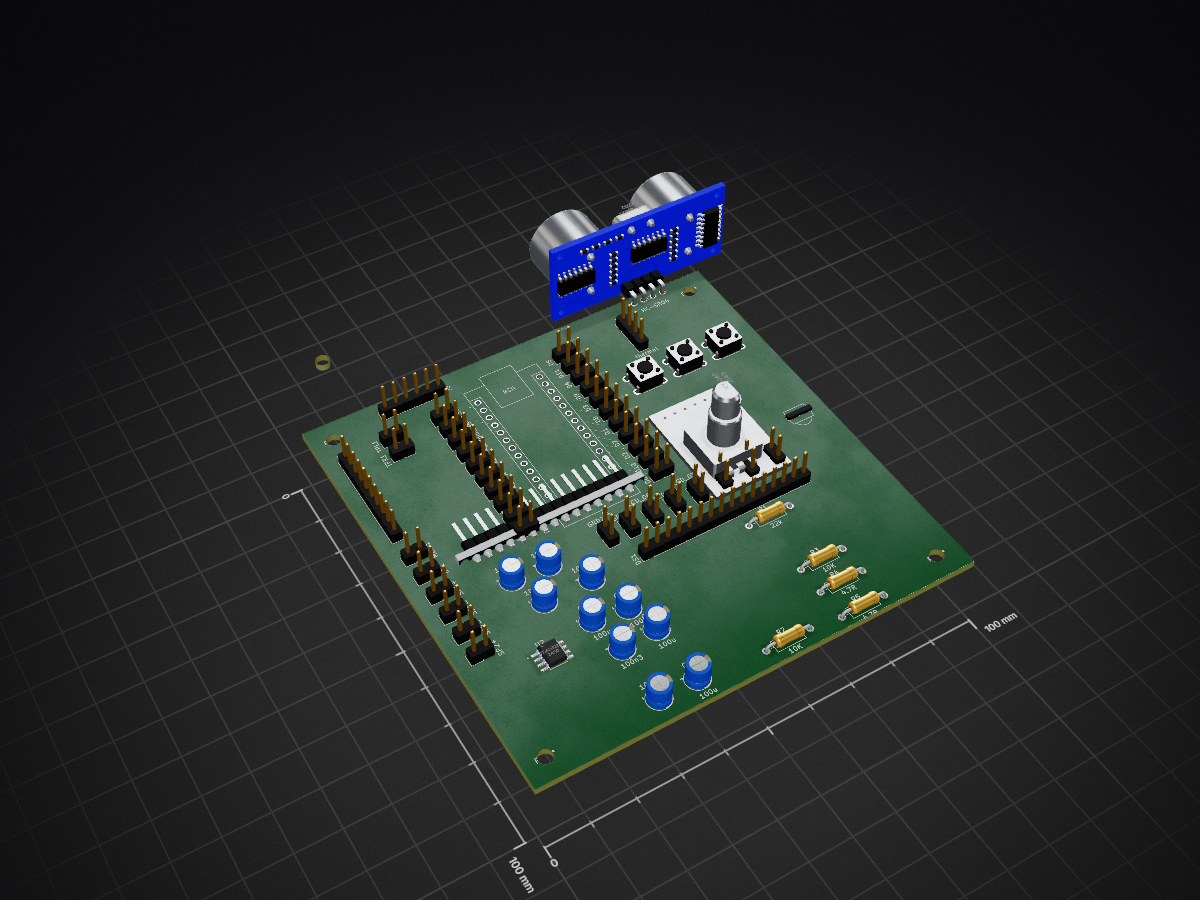
Fm radio is an open-source printed circuit board by WaseemALTamer, from the WaseemALTamer/EmbeddedControlSystem repository on GitHub. It is a 2-layer board of 100 × 100 mm with 69 parts on 54 nets, routed with 71 tracks and 0 vias.
It is built around the TDA2822D, HC-SR04 and D12. Its parts include 15 diodes, 5 resistors, 5 ICs, 5 connectors and 4 capacitors. It belongs with the radio and wireless boards and the AVR (ATmega, ATtiny) boards of this library.
| Qty | Value | Footprint | References |
|---|---|---|---|
| 4 | 100u | Capacitor_THT:CP_Radial_D5.0mm_P2.50mm | C1, C2, C3, C4 |
| 3 | C | Capacitor_THT:CP_Radial_D5.0mm_P2.50mm | 100n1, 100n2, 100n3 |
| 3 | C_Polarized | Capacitor_THT:CP_Radial_D5.0mm_P2.50mm | 10u1, 10u2, 10u3 |
| 3 | D2 | Connector_PinHeader_2.54mm:PinHeader_1x02_P2.54mm_Vertical | 5V1, D6, LCD_D5 |
| 3 | GRD | Connector_PinHeader_2.54mm:PinHeader_1x02_P2.54mm_Vertical | GRD1, GRD2, GRD3 |
| 2 | +V OUT | Connector_PinHeader_2.54mm:PinHeader_1x02_P2.54mm_Vertical | SP1+, SP2+ |
| 2 | -V OUT | Connector_PinHeader_2.54mm:PinHeader_1x02_P2.54mm_Vertical | SP1-, SP2- |
| 2 | 10K | Resistor_THT:R_Axial_DIN0207_L6.3mm_D2.5mm_P10.16mm_Horizontal | R2, R3 |
| 2 | 4.7R | Resistor_THT:R_Axial_DIN0207_L6.3mm_D2.5mm_P10.16mm_Horizontal | R4, R5 |
| 2 | D10 | Connector_PinHeader_2.54mm:PinHeader_1x02_P2.54mm_Vertical | D4, LCD_D2 |
| 2 | D11 | Connector_PinHeader_2.54mm:PinHeader_1x02_P2.54mm_Vertical | D11, LCD_D4 |
| 2 | D12 | Connector_PinHeader_2.54mm:PinHeader_1x02_P2.54mm_Vertical | D5, LCD_D1 |
| 2 | D3 | Connector_PinHeader_2.54mm:PinHeader_1x02_P2.54mm_Vertical | D10, LCD_D6 |
| 2 | D9 | Connector_PinHeader_2.54mm:PinHeader_1x02_P2.54mm_Vertical | D9, LCD_D3 |
| 2 | TestPoint_2Pole | Connector_PinHeader_2.54mm:PinHeader_1x02_P2.54mm_Vertical | Mute1, Power1 |
| 1 | 22k | Resistor_THT:R_Axial_DIN0207_L6.3mm_D2.5mm_P10.16mm_Horizontal | R1 |
| 1 | 3.3V | Connector_PinHeader_2.54mm:PinHeader_1x02_P2.54mm_Vertical | 3.3V1 |
| 1 | A0 | Connector_PinHeader_2.54mm:PinHeader_1x02_P2.54mm_Vertical | A5 |
| 1 | A1 | Connector_PinHeader_2.54mm:PinHeader_1x02_P2.54mm_Vertical | Arduino_A1 |
| 1 | A2 | Connector_PinHeader_2.54mm:PinHeader_1x02_P2.54mm_Vertical | A3 |
| 1 | A3 | Connector_PinHeader_2.54mm:PinHeader_1x02_P2.54mm_Vertical | A6 |
| 1 | A4 | Connector_PinHeader_2.54mm:PinHeader_1x02_P2.54mm_Vertical | A4 |
| 1 | A5 | Connector_PinHeader_2.54mm:PinHeader_1x02_P2.54mm_Vertical | A2 |
| 1 | Arduino_Nano_v3.x | Module:Arduino_Nano | A1 |
| 1 | Battery | Connector_PinHeader_2.54mm:PinHeader_1x02_P2.54mm_Vertical | BT1 |
| 1 | Button _enter | Button_Switch_THT:SW_PUSH_6mm | J1 |
| 1 | Button _left | Button_Switch_THT:SW_PUSH_6mm | J3 |
| 1 | Button _right | Button_Switch_THT:SW_PUSH_6mm | J2 |
| 1 | D4 | Connector_PinHeader_2.54mm:PinHeader_1x02_P2.54mm_Vertical | D2 |
| 1 | D5 | Connector_PinHeader_2.54mm:PinHeader_1x02_P2.54mm_Vertical | D7 |
| 1 | D6 | Connector_PinHeader_2.54mm:PinHeader_1x02_P2.54mm_Vertical | D1 |
| 1 | D7 | Connector_PinHeader_2.54mm:PinHeader_1x02_P2.54mm_Vertical | D8 |
| 1 | D8 | Connector_PinHeader_2.54mm:PinHeader_1x02_P2.54mm_Vertical | D3 |
| 1 | HC-SR04 | HC-SR04:XCVR_HC-SR04 | U1 |
| 1 | KY-040 | KY-040:KY-040-PORT | U3 |
| 1 | Left in | Connector_PinHeader_2.54mm:PinHeader_1x02_P2.54mm_Vertical | TPL1 |
| 1 | RTC | Connector_PinHeader_2.54mm:PinHeader_1x06_P2.54mm_Vertical | J5 |
| 1 | Right in | Connector_PinHeader_2.54mm:PinHeader_1x02_P2.54mm_Vertical | TPR1 |
| 1 | TDA2822D | Library:TDA2822D | U2 |
| 1 | TSOP1838 | TSOP1838:TSOP18XX | U4 |
| 1 | WC1602A | Connector_PinHeader_2.54mm:PinHeader_1x16_P2.54mm_Vertical | DS1 |
| 1 | thermal | Connector_PinHeader_2.54mm:PinHeader_1x04_P2.54mm_Vertical | J4 |
| 1 | ~ | Connector_PinHeader_2.54mm:PinHeader_1x10_P2.54mm_Vertical | U5 |
The 64 most common of 69 parts.

GadgetReboot/ESP32-A1S
Breakout PCB for the ESP32-A1S module including an audio amp and basic GPIO headers, USB interface

ksmola/PriusG2
Inverter control board for Toyota Prius Gen 2 (XW20) inverter. Some of the schematics are based on Johannes Huebner's work found here. Running openinverter firmware.

zartarn15/hubble-metal-detector
STM32-based digital metal detector with custom hardware and embedded DSP firmware.

doobedoobedo/Huebner_Inverter
KiCAD port of https://github.com/jsphuebner/inverter-hardware mainboard V1.2

OpenRetroHQ/sega-gamegear-audio-original
Sega Game Gear Audio Original - Remake of the original TDA2882M audio board for the game gear


SL-RU/simple_headphones_dac
Simple board with DAC cs4335 and amplifier TDA2822

It measures 100 × 100 mm and has 2 copper layers, 1.6 mm thick.
69 parts, built around the TDA2822D, HC-SR04 and D12. The full list of its parts is on this page, with links to each part's symbol and footprint where PCBKit's library has them.
From the WaseemALTamer/EmbeddedControlSystem repository on GitHub, at the commit this page was made from: the board is PCB/Version-1/Fm_radio.kicad_pcb and its schematic PCB/Version-1/Encoder.kicad_sch. PCBKit opens the board in the browser, with nothing to install.
Its repository states no licence, so its author keeps all rights: ask WaseemALTamer before reusing the design.