2 layers91.9 × 70.1 mm
 WEEE-Open/psutap
Device for PSU power lines inspection and monitoring
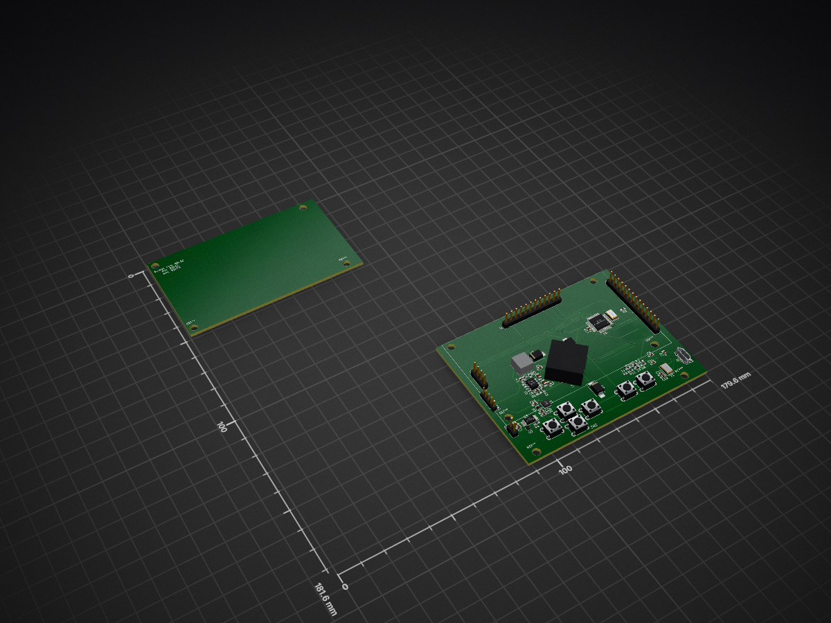
PSUtap digital is an open-source printed circuit board by WEEE-Open, from the WEEE-Open/psutap repository on GitHub. It is a 2-layer board of 179.6 × 181.6 mm with 90 parts on 80 nets, routed with 707 tracks and 69 vias.
It is built around the ATMEGA328P-AU, CH340G and SI6926ADQ, with the MBRS130LT3G-F and CTX33-3A-R among its other parts. Its parts include 28 capacitors, 24 resistors, 7 switches, 6 ICs and 5 diodes. It belongs with the AVR (ATmega, ATtiny) boards of this library.


The PSUtap is a battery powered device designed to sit between the PSU (power supply unit) and the motherboard of a desktop computer.
It's purpose is to constantly monitor the power lines (voltage and current) to detect power related issues: short circuits, open circuits, overloads, overvoltages, etc...
It taps the lines from the main 24 pin ATX connector and the lines from another 4 pin connector to monitor:
The device is divided into three different boards, which are mounted on top of each other. From the bottom up, they are:
The three are connected through male/female headers and communicate through an SPI interface.
This board gets its name from the fact that it has current sensing ICs, voltage sensing voltage dividers and an ADC to transmit the data to the digital board.
For the current sensing, we've used some LT6105 ICs, which are essentially (differential) voltage controlled current sources. The configuration in our board is not much different than the typical application shown in the schematic.
For the voltage sensing, we've used some regular voltage dividers, with a bit of margin so that we can also detect overvoltages.
The ADC is an AD7708, which is a delta-sigma, 16 bits, 10 channels ADC with integrated SPI interface, which is why we chose it, so that we could easily connect it to a uC without using too many wires.
This board contains the uC, the brain of the entire device, a CH340G USB to serial converter, the battery charging and protection circuit, a USB port and some buttons for the user input.
The used uC is an ATmega328P, which will be flashed with the Arduino bootloader so that it can be easily programmed through the Arduino IDE.
Its main tasks are:
The screen module is a 240x320 2.8'' LCD, and the serial number is tjctm24028-spi.
It's purpose is to show the user all the measured voltages and currents at once, so that a problem related with the power lines can be located very quickly, and also graph the voltages and currents wrt time.
| Qty | Value | Footprint | References |
|---|---|---|---|
| 15 | 100n | Capacitor_SMD:C_0603_1608Metric_Pad1.05x0.95mm_HandSolder | C2, C4, C7, C10, C11, C13, C14, C16, C20, C21, C22, C23, C25, C27, C28 |
| 12 | 10k | Resistor_SMD:R_0603_1608Metric_Pad1.05x0.95mm_HandSolder | R13, R14, R15, R16, R17, R18, R19, R20, R21, R22, R23, R24 |
| 6 | 1k | Resistor_SMD:R_0603_1608Metric_Pad1.05x0.95mm_HandSolder | R2, R7, R8, R10, R11, R12 |
| 4 | 10p | Capacitor_SMD:C_0603_1608Metric_Pad1.05x0.95mm_HandSolder | C15, C17, C18, C19 |
| 3 | MBRS130LT3G | Diode_SMD:D_SMB_Handsoldering | D1, D2, D3 |
| 2 | 100k | Resistor_SMD:R_0603_1608Metric_Pad1.05x0.95mm_HandSolder | R4, R5 |
| 2 | 1u | Capacitor_SMD:C_0603_1608Metric_Pad1.05x0.95mm_HandSolder | C9, C26 |
| 2 | 22u | Capacitor_SMD:C_0805_2012Metric_Pad1.15x1.40mm_HandSolder | C1, C5 |
| 1 | 0.2 | Resistor_SMD:R_0603_1608Metric_Pad1.05x0.95mm_HandSolder | R3 |
| 1 | 100 | Resistor_SMD:R_0603_1608Metric_Pad1.05x0.95mm_HandSolder | R9 |
| 1 | 10n | Capacitor_SMD:C_0603_1608Metric_Pad1.05x0.95mm_HandSolder | C8 |
| 1 | 10u | Inductor_SMD:L_Wuerth_MAPI-3012 | L1 |
| 1 | 12MHz | Crystal:Crystal_SMD_5032-2Pin_5.0x3.2mm | Y1 |
| 1 | 16MHz | Crystal:Crystal_SMD_5032-2Pin_5.0x3.2mm | Y2 |
| 1 | 2.2u | Capacitor_SMD:C_0603_1608Metric_Pad1.05x0.95mm_HandSolder | C3 |
| 1 | 220n | Capacitor_SMD:C_0603_1608Metric_Pad1.05x0.95mm_HandSolder | C6 |
| 1 | 22u | Capacitor_SMD:C_0603_1608Metric_Pad1.05x0.95mm_HandSolder | C24 |
| 1 | 231.8k | Potentiometer_THT:TRIM_3362P-1-304 | RV1 |
| 1 | 24 | Resistor_SMD:R_0603_1608Metric_Pad1.05x0.95mm_HandSolder | R6 |
| 1 | 330 | Resistor_SMD:R_0603_1608Metric_Pad1.05x0.95mm_HandSolder | R1 |
| 1 | 4.7u | Capacitor_SMD:C_0603_1608Metric_Pad1.05x0.95mm_HandSolder | C12 |
| 1 | A | Button_Switch_THT:SW_PUSH_6mm | SW6 |
| 1 | ADC_board_SPI | Connector_PinHeader_2.54mm:PinHeader_1x12_P2.54mm_Vertical | J2 |
| 1 | ATmega328P-AU | Package_QFP:TQFP-32_7x7mm_P0.8mm | U5 |
| 1 | B | Button_Switch_THT:SW_PUSH_6mm | SW5 |
| 1 | BQ2973 | Package_SON:WSON-6_1.5x1.5mm_P0.5mm | U2 |
| 1 | Battery_Cell | Connector_PinHeader_2.54mm:PinHeader_1x02_P2.54mm_Vertical | BT1 |
| 1 | CH340G | Package_SO:SOIC-16_3.9x9.9mm_P1.27mm | U4 |
| 1 | CTX33-3 | Transformer_SMD:IND_CTX33-3-R | T1 |
| 1 | Down | Button_Switch_THT:SW_PUSH_6mm | SW2 |
| 1 | LT1512 | Package_SO:SO-8_3.9x4.9mm_P1.27mm | U1 |
| 1 | LTC3525-5 | Package_TO_SOT_SMD:SOT-363_SC-70-6 | U6 |
| 1 | Left | Button_Switch_THT:SW_PUSH_6mm | SW3 |
| 1 | RX | Diode_SMD:D_0603_1608Metric_Pad1.05x0.95mm_HandSolder | D5 |
| 1 | Right | Button_Switch_THT:SW_PUSH_6mm | SW4 |
| 1 | SD_card_SPI | Connector_PinHeader_2.54mm:PinHeader_1x04_P2.54mm_Vertical | J3 |
| 1 | SW_DPST_x2 | Connector_PinHeader_2.00mm:PinHeader_1x05_P2.00mm_Vertical | SW7 |
| 1 | Screen_SPI | Connector_PinHeader_2.54mm:PinHeader_1x14_P2.54mm_Vertical | J4 |
| 1 | Si6926ADQ | Package_SO:TSSOP-8_4.4x3mm_P0.65mm | U3 |
| 1 | TX | Diode_SMD:D_0603_1608Metric_Pad1.05x0.95mm_HandSolder | D4 |
| 1 | USB_B_Micro | Connector_USB:USB_Micro-B_Molex-105017-0001 | J1 |
| 1 | Up | Button_Switch_THT:SW_PUSH_6mm | SW1 |
The 80 most common of 90 parts.


Akhilesh-design-02/STM32F407-Hardware-Design
4-layer STM32F407 mixed-signal PCB design featuring I2C/I2S/USB interfaces, SGP40 & SHT40 sensors, power plane splits, and star grounding for noise isolation.


YJM00/Mixed-Signal-Board-PI-SI-PCB-
즉, 이 프로젝트는 단순 회로 작성이 아니라 System-level Requirement를 기반으로 실제 제작 가능한 형태의 STM32 Mixed-Signal 보드를 설계한 HW 설계 프로젝트입니다.


4x1md/vx8_gps
DIY GPS module for Yaesu VX-8DR/VX-8DE handheld transceiver.
It measures 179.6 × 181.6 mm and has 2 copper layers, 1.6 mm thick.
90 parts, built around the ATMEGA328P-AU, CH340G, SI6926ADQ and MBRS130LT3G-F. The full list of its parts is on this page, with links to each part's symbol and footprint where PCBKit's library has them.
From the WEEE-Open/psutap repository on GitHub, at the commit this page was made from: the board is PSUtap_digital/PSUtap_digital.kicad_pcb. PCBKit opens the board in the browser, with nothing to install.
Its repository states no licence, so its author keeps all rights: ask WEEE-Open before reusing the design.