2 layers81.8 × 80.2 mm

 Vaaarad07/PCB_Designs10
A repo with STM32 based PCB designs
Audio player is an open-source printed circuit board by Vaaarad07, from the Vaaarad07/PCB_Designs repository on GitHub, published under the MIT licence. It is a 2-layer board of 74 × 63.1 mm with 87 parts on 83 nets, routed with 726 tracks and 78 vias.
It is built around the RP2040, 74LVC1G125 and MAX98357AETE+T, with the W25Q128JVSIQ, AMS1117-3.3 and AMS1117-5.0 among its other parts. Its parts include 33 capacitors, 16 resistors, 9 ICs, 8 connectors and 4 diodes. It belongs with the audio and music boards and the RP2040 and STM32 boards of this library.


This repo contains the PCB files designed by @Vaaarad07. All of the designs are completely produced in KiCad 6, and each project directory contains the respective KiCad schematic and layout files. All of the PCB projects are manufactured and tested for their respective functionalities. I am open for any kind of feedback, suggestion or discussion.
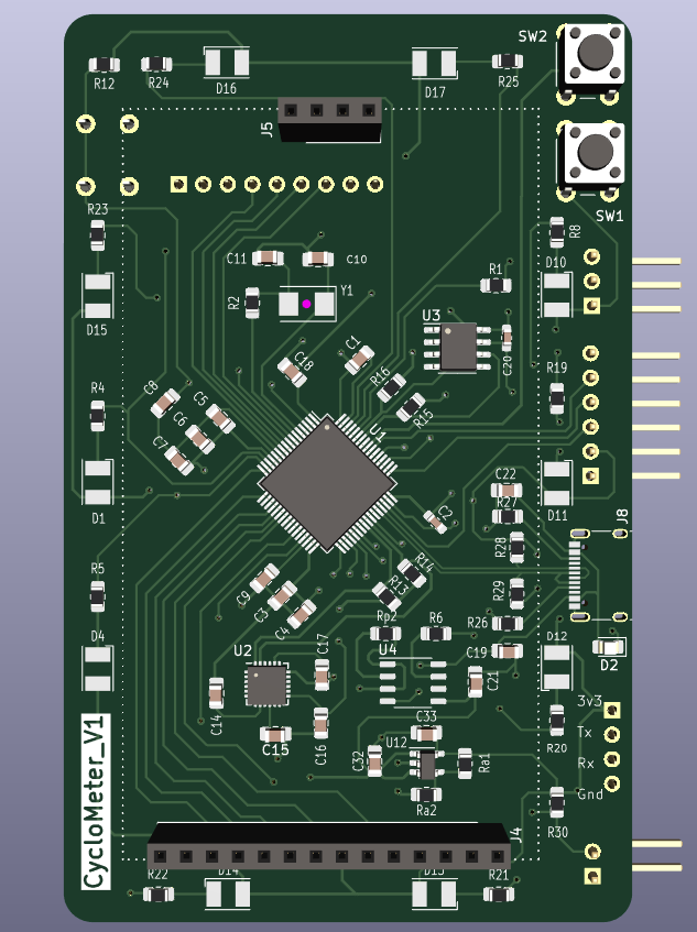
Cyclometer is a minimal dashhborad for bicycles used to accurately measure, store and display the speed, distance & time of the bike rides. The board uses STM32F446 controller.
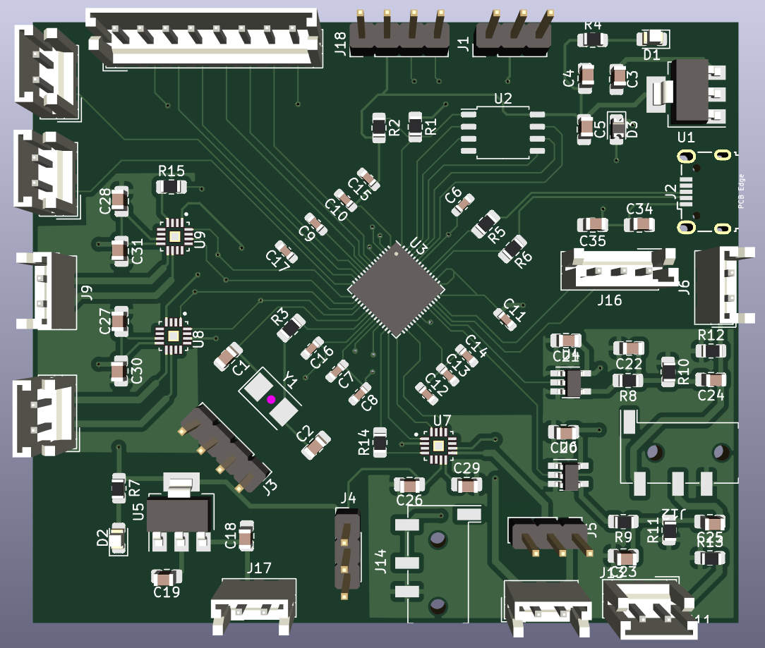
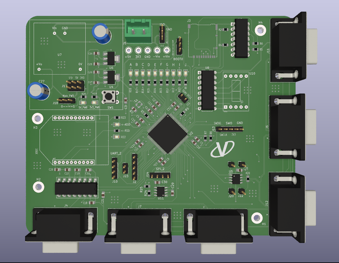
This is a custom made 4-layer board using STM32F407, designed for Vegapod Hyperloop, a student team. The board is a part of a vehicle control system as the Master control Unit. The board connects to 5 separate vehicle control unit boards using DB9 cables and connectors over CAN bus,which are responsible for handling their sub-system specific functions.
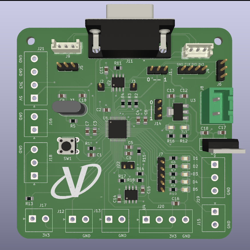
This is a custom made 2-Layer board using STM32F103, designed for Vegapod Hyperloop, a student team. The board is a part of a vehicle control system as a vehicle control Unit. The board connects to the Master vehicle control unit using DB9 cable and connector over CAN bus
This is a custom made 2-Layer board using STM32F103, designed for Vegapod Hyperloop, a student team. The board is a part of a vehicle control system as a vehicle control Unit responsible for control of the inverter sub-system. The board connects to the Master vehicle control unit using DB9 cable and connector over CAN bus
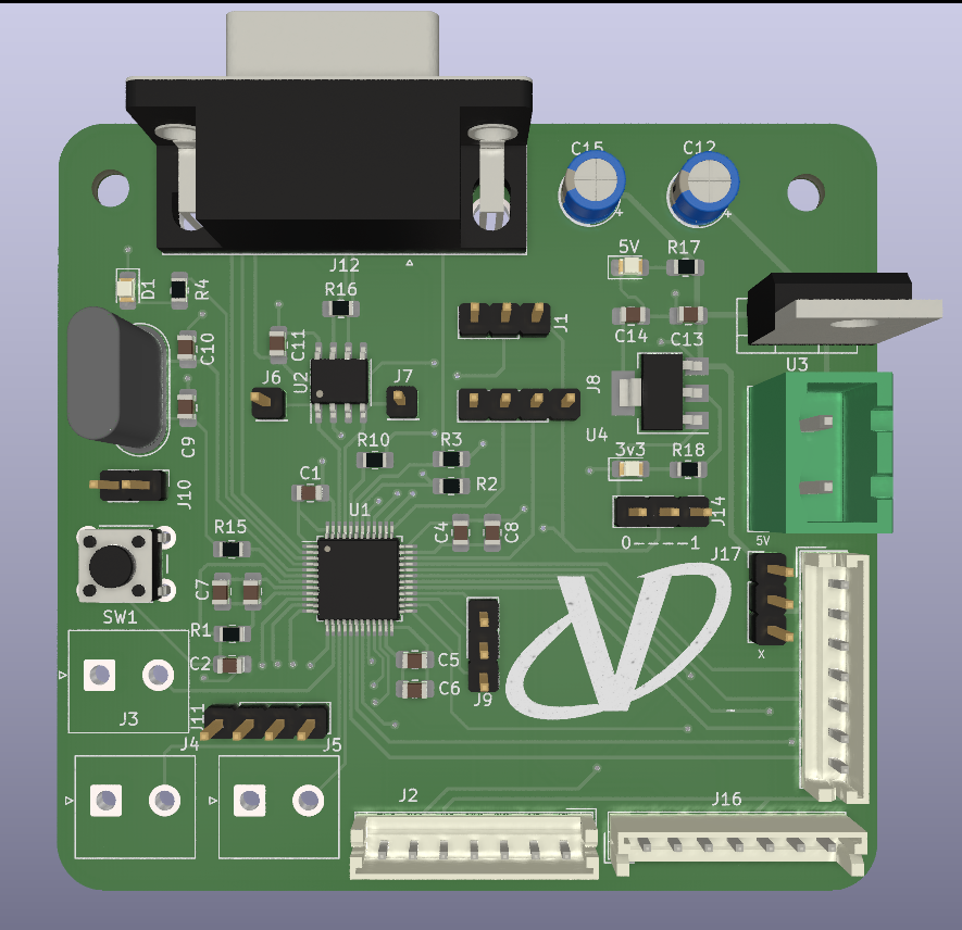
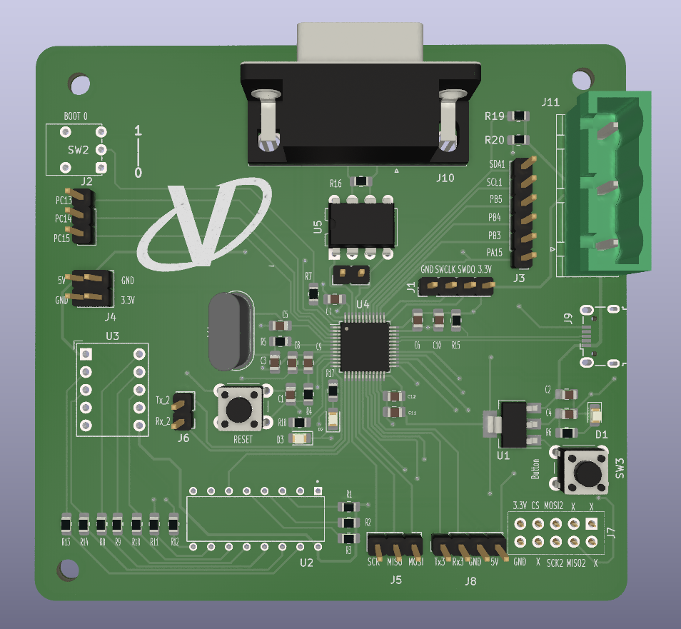
This is a custom made 2-Layer board using the STM32F103 , designed for Vegapod Hyperloop, a student team. The board is designed for testing procedures of various peripherals of the controller and verification of the designed architecture of a vehicle control system.
| Qty | Value | Footprint | References |
|---|---|---|---|
| 10 | 100n | Capacitor_SMD:C_0603_1608Metric_Pad1.08x0.95mm_HandSolder | C6, C8, C9, C10, C12, C13, C14, C15, C16, C17 |
| 10 | 10u | Capacitor_SMD:C_0805_2012Metric_Pad1.18x1.45mm_HandSolder | C3, C4, C18, C19, C20, C21, C26, C27, C28, C35 |
| 6 | 100n | Capacitor_SMD:C_0805_2012Metric_Pad1.18x1.45mm_HandSolder | C1, C2, C5, C22, C23, C34 |
| 5 | 1k | Resistor_SMD:R_0805_2012Metric_Pad1.20x1.40mm_HandSolder | R1, R3, R4, R7, R16 |
| 5 | Conn_01x02_Pin | Connector_PinHeader_2.54mm:PinHeader_1x02_P2.54mm_Vertical | A1, A2, J6, Z1, Z2 |
| 5 | Conn_01x03_Pin | Connector_PinHeader_2.54mm:PinHeader_1x03_P2.54mm_Vertical | J1, J4, J5, J15, J16 |
| 4 | Conn_01x02_Pin | Connector_JST:JST_EH_B2B-EH-A_1x02_P2.50mm_Vertical | B1, J17, X1, X2 |
| 3 | 0.1u | Capacitor_SMD:C_0805_2012Metric_Pad1.18x1.45mm_HandSolder | C29, C30, C31 |
| 3 | LED | LED_SMD:LED_0805_2012Metric_Pad1.15x1.40mm_HandSolder | D1, D2, D4 |
| 3 | MAX98357AETE_ | lib:QFN50P300X300X80-17N | U7, U8, U9 |
| 2 | 1.8k | Resistor_SMD:R_0805_2012Metric_Pad1.20x1.40mm_HandSolder | R12, R13 |
| 2 | 100 | Resistor_SMD:R_0805_2012Metric_Pad1.20x1.40mm_HandSolder | R10, R11 |
| 2 | 1u | Capacitor_SMD:C_0603_1608Metric_Pad1.08x0.95mm_HandSolder | C7, C11 |
| 2 | 220 | Resistor_SMD:R_0805_2012Metric_Pad1.20x1.40mm_HandSolder | R8, R9 |
| 2 | 27.4 | Resistor_SMD:R_0805_2012Metric_Pad1.20x1.40mm_HandSolder | R5, R6 |
| 2 | 47u | Capacitor_SMD:C_0805_2012Metric_Pad1.18x1.45mm_HandSolder | C24, C25 |
| 2 | 74LVC1G125 | Package_TO_SOT_SMD:SOT-23-5_HandSoldering | U4, U6 |
| 2 | AudioJack4 | Connector_Audio:Jack_3.5mm_KoreanHropartsElec_PJ-320D-4A_Horizontal | B2, X3 |
| 2 | FerriteBead_Small | Inductor_SMD:L_0805_2012Metric_Pad1.05x1.20mm_HandSolder | FB1, FB2 |
| 2 | MountingHole_Pad | MountingHole:MountingHole_2.2mm_M2 | H1, H4 |
| 1 | 300k | Resistor_SMD:R_0805_2012Metric_Pad1.20x1.40mm_HandSolder | R14 |
| 1 | 69.8k | Resistor_SMD:R_0805_2012Metric_Pad1.20x1.40mm_HandSolder | R15 |
| 1 | AMS1117-3.3 | Package_TO_SOT_SMD:SOT-223-3_TabPin2 | U1 |
| 1 | AMS1117-5.0 | Package_TO_SOT_SMD:SOT-223-3_TabPin2 | U5 |
| 1 | Conn_01x04_Pin | Connector_PinHeader_2.54mm:PinHeader_1x04_P2.54mm_Vertical | J3 |
| 1 | Conn_01x12_Pin | Connector_PinHeader_2.54mm:PinHeader_1x12_P2.54mm_Vertical | J2 |
| 1 | Crystal | Crystal:Crystal_SMD_5032-2Pin_5.0x3.2mm | Y1 |
| 1 | D | Diode_SMD:D_0805_2012Metric_Pad1.15x1.40mm_HandSolder | D3 |
| 1 | DNF | Resistor_SMD:R_0805_2012Metric_Pad1.20x1.40mm_HandSolder | R2 |
| 1 | LOGO | lib:pic | G*** |
| 1 | RP2040 | Package_DFN_QFN:QFN-56-1EP_7x7mm_P0.4mm_EP3.2x3.2mm | U3 |
| 1 | USB3076-XX-X_REVC5 | lib:USB-B_varad | J19 |
| 1 | W25Q128JVS | Package_SO:SOIC-8_5.23x5.23mm_P1.27mm | U2 |

victorhook/asac-fc
asac fc is an rp2040 based flight controller made for FPV drone flying

niektb/sluisbrinkie-eurorack-published
Published Modules of the Sluisbrinkie project

antmicro/audio-latency-tester-board
This project contains open hardware design files for an audio latency processing board. The system allows driving an external speaker and collecting audio samples from a pair of PDM or I2S microphones.

alph4345/test
TrinketCore puts everything a small rechargeable gadget needs on one 40 × 60 mm board, ready to order assembled from PCBWay:


Kirg5/2040Inverter
RP2040 Based BLDC Inverter for sensored motors, capable of putting out 50a 100v

AtrivaTECH/picuno
A repo of all files for the pic uno RP2040+Arduino UNO derivative by ESCcrasci and AtrivaTECH

dario0603/Hotplate
Hotplate is a DIY electronics project focused on the design and development of a hotplate and its associated control electronics.
It measures 74 × 63.1 mm and has 2 copper layers, 1.6 mm thick.
87 parts, built around the RP2040, 74LVC1G125, MAX98357AETE+T and W25Q128JVSIQ. The full list of its parts is on this page, with links to each part's symbol and footprint where PCBKit's library has them.
From the Vaaarad07/PCB_Designs repository on GitHub, at the commit this page was made from: the board is RP2040/Audio_player.kicad_pcb and its schematic Cyclometer/Cyclometer_v1.kicad_sch. PCBKit opens the board in the browser, with nothing to install.
Its repository publishes it under the MIT licence: you may reuse it on that licence's terms (keep the author's notice, and for a copyleft licence share your changes alike).
