4 layers68.6 × 53.3 mm
Phyduino pico
perc-sw/phyduino_pico
CAD files for the student workshop Phyduino Pico Arduino IDE compatible board.
129 partsGPL-3.0

 UofTPhyEssSW/Student-Workshop-Course-L12
University of Toronto, Dept. of Physics, Electronic Support Services - Student Workshop Course L1 course files
Phyduino pico is an open-source printed circuit board by UofTPhyEssSW, from the UofTPhyEssSW/Student-Workshop-Course-L1 repository on GitHub. It is a 4-layer board of 68.6 × 53.3 mm with 130 parts on 122 nets, routed with 1,009 tracks and 241 vias.
It is built around the RP2040, MAX11635EEE+T and TPS2121RUXT, with the USBLC6-2P6, SS24FL and AONR21321 among its other parts. Its parts include 51 resistors, 44 capacitors, 9 ICs, 8 diodes and 6 connectors. It belongs with the power boards and the RP2040 boards of this library.


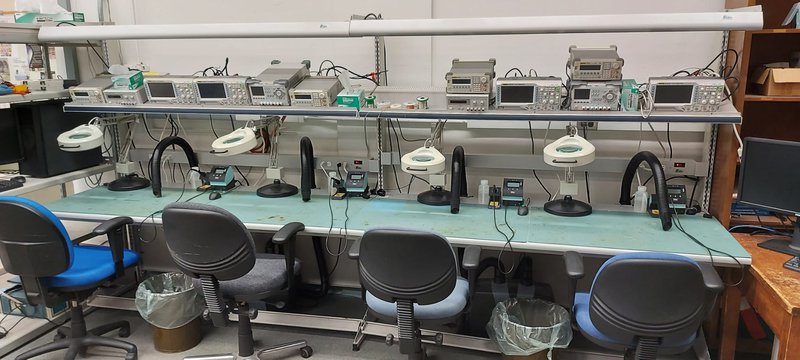
This is a non-credit Introduction to Electronics Graduate course for University of Toronto, Physics Gradute students, held over four, three-hour sessions which consist of one hour of lecture and two hours of practical time.
This course is an Introduction to Electronics course where the student will learn how to solder through hole and surface mount components as well as learn about data acquisition (DAQ), power supplies, digital and analog electronics circuits. During the course the students will build a single channel DAQ board that measures ambient temperature and an Arduino Uno clone, which is theirs to take home. Please note that class has a maximum of 4 students and must have a minimum of 2 students registered for the class to be held.
If the class is full and your are still interested, please add yourself to the waiting list. We will try to schedule another course as soon as possible.
The Arduino IDE 2 is used to demostrate the Phyduino Pico and Analog Front End board. Since these are custom boards a new board manager and libraries must be installed in the IDE for the boards to be programmed. (instructions here).
All circuit boards for this course were designed using KiCad EDA opensource software to make the schematic and PCB design files easy to access for the student. It's not requirement for the student to understand schematic symbols or PCB design the files are there for reference.
| Qty | Value | Footprint | References |
|---|---|---|---|
| 13 | 0.1µF | Capacitor_SMD:C_0402_1005Metric_Pad0.74x0.62mm_HandSolder | C14, C16, C18, C20, C21, C22, C23, C24, C25, C26, C30, C35, C40 |
| 8 | 4.7KΩ | Resistor_SMD:R_0402_1005Metric_Pad0.72x0.64mm_HandSolder | R13, R16, R17, R20, R38, R39, R42, R45 |
| 7 | 0.1µF | Capacitor_SMD:C_0805_2012Metric_Pad1.18x1.45mm_HandSolder | C3, C6, C27, C31, C34, C36, C37 |
| 5 | 1µF | Capacitor_SMD:C_0402_1005Metric_Pad0.74x0.62mm_HandSolder | C17, C19, C28, C29, C32 |
| 4 | 10,000pF | Capacitor_SMD:C_0402_1005Metric_Pad0.74x0.62mm_HandSolder | C41, C42, C43, C44 |
| 4 | 10.2KΩ | Resistor_SMD:R_0805_2012Metric_Pad1.20x1.40mm_HandSolder | R8, R10, R14, R32 |
| 4 | 100KΩ | Resistor_SMD:R_0402_1005Metric_Pad0.72x0.64mm_HandSolder | R26, R51, R52, R53 |
| 4 | 10Ω | Resistor_SMD:R_0402_1005Metric_Pad0.72x0.64mm_HandSolder | R47, R48, R49, R50 |
| 4 | 22µF | Capacitor_SMD:C_0805_2012Metric_Pad1.18x1.45mm_HandSolder | C9, C10, C11, C12 |
| 4 | 6.98KΩ | Resistor_SMD:R_0805_2012Metric_Pad1.20x1.40mm_HandSolder | R2, R3, R5, R6 |
| 3 | 1KΩ | Resistor_SMD:R_0805_2012Metric_Pad1.20x1.40mm_HandSolder | R33, R34, R35 |
| 3 | MountingHole | MountingHole:MountingHole_3.2mm_M3 | H1, H2, H3 |
| 2 | 10pF | Capacitor_SMD:C_0805_2012Metric_Pad1.18x1.45mm_HandSolder | C4, C7 |
| 2 | 18µH | Inductors - Coilcraft:MSS1246_Handsolder | L1, L2 |
| 2 | 19.6KΩ | Resistor_SMD:R_0402_1005Metric_Pad0.72x0.64mm_HandSolder | R40, R44 |
| 2 | 1KΩ | Resistor_SMD:R_0402_1005Metric_Pad0.72x0.64mm_HandSolder | R24, R25 |
| 2 | 27pF | Capacitor_SMD:C_0402_1005Metric_Pad0.74x0.62mm_HandSolder | C13, C15 |
| 2 | 27Ω | Resistor_SMD:R_0402_1005Metric_Pad0.72x0.64mm_HandSolder | R18, R19 |
| 2 | 4.7nF | Capacitor_SMD:C_0805_2012Metric_Pad1.18x1.45mm_HandSolder | C38, C39 |
| 2 | 4.7µF | Capacitor_SMD:C_1210_3225Metric_Pad1.33x2.70mm_HandSolder | C1, C2 |
| 2 | 5.1K | Capacitor_SMD:C_0402_1005Metric_Pad0.74x0.62mm_HandSolder | R21, R22 |
| 2 | 560 | Resistor_SMD:R_0402_1005Metric_Pad0.72x0.64mm_HandSolder | R11, R12 |
| 2 | 8.2nF | Capacitor_SMD:C_0805_2012Metric_Pad1.18x1.45mm_HandSolder | C5, C8 |
| 2 | Conn_01x08 | Connector_PinSocket_2.54mm:PinSocket_1x08_P2.54mm_Vertical | J2, J5 |
| 2 | GREEN | LED_SMD:LED_0805_2012Metric_Pad1.15x1.40mm_HandSolder | D5, D8 |
| 2 | GRN | LED_SMD:LED_0402_1005Metric_Pad0.77x0.64mm_HandSolder | D6, D7 |
| 2 | SS24FL | Diode_SMD:D_SOD-123 | D3, D4 |
| 2 | TPS54231DR | Package_SO:SOIC-8_3.9x4.9mm_P1.27mm | U1, U2 |
| 1 | 1.96K | Resistor_SMD:R_0805_2012Metric_Pad1.20x1.40mm_HandSolder | R9 |
| 1 | 100KΩ | Resistor_SMD:R_0805_2012Metric_Pad1.20x1.40mm_HandSolder | R15 |
| 1 | 100Ω | Resistor_SMD:R_0402_1005Metric_Pad0.72x0.64mm_HandSolder | R29 |
| 1 | 124Ω | Resistor_SMD:R_0805_2012Metric_Pad1.20x1.40mm_HandSolder | R23 |
| 1 | 18.2KΩ | Resistor_SMD:R_0805_2012Metric_Pad1.20x1.40mm_HandSolder | R1 |
| 1 | 1MΩ | Resistor_SMD:R_0805_2012Metric_Pad1.20x1.40mm_HandSolder | R31 |
| 1 | 1µF | Capacitor_SMD:C_0805_2012Metric_Pad1.18x1.45mm_HandSolder | C33 |
| 1 | 2.0KΩ | Resistor_SMD:R_0402_1005Metric_Pad0.72x0.64mm_HandSolder | R28 |
| 1 | 22KΩ | Resistor_SMD:R_0402_1005Metric_Pad0.72x0.64mm_HandSolder | R27 |
| 1 | 2KΩ | Resistor_SMD:R_0805_2012Metric_Pad1.20x1.40mm_HandSolder | R37 |
| 1 | 3.24KΩ | Resistor_SMD:R_0805_2012Metric_Pad1.20x1.40mm_HandSolder | R7 |
| 1 | 31.6KΩ | Resistor_SMD:R_0805_2012Metric_Pad1.20x1.40mm_HandSolder | R4 |
| 1 | 42.2KΩ | Resistor_SMD:R_0402_1005Metric_Pad0.72x0.64mm_HandSolder | R46 |
| 1 | 560Ω | Resistor_SMD:R_0805_2012Metric_Pad1.20x1.40mm_HandSolder | R30 |
| 1 | 632723300011 | Connectors - USB:Wurth_USBC_R_632723100011 | J6 |
| 1 | 649Ω | Resistor_SMD:R_0805_2012Metric_Pad1.20x1.40mm_HandSolder | R36 |
| 1 | AONR21321 | Pacakge Lib - DFN:AONR21321_DFN_3x3 | Q1 |
| 1 | AYZ0102AGRLC | Mechincal_Switches:AYZ0102AGRLC_SMD | SW1 |
| 1 | BLM15AG221SH1D | Inductor_SMD:L_0402_1005Metric_Pad0.77x0.64mm_HandSolder | FB1 |
| 1 | Conn_01x05 | Connector_PinSocket_2.54mm:PinSocket_1x05_P2.54mm_Vertical | J1 |
| 1 | Conn_01x06 | Connector_PinSocket_2.54mm:PinSocket_1x06_P2.54mm_Vertical | J4 |
| 1 | Conn_01x10 | Connector_PinSocket_2.54mm:PinSocket_1x10_P2.54mm_Vertical | J3 |
| 1 | H130B-12.000-18-3030-TR | Oscillator:Oscillator_SMD_Abracon_ASE-4Pin_3.2x2.5mm | Y1 |
| 1 | LM4040DIM3-2.0/NOPB | Package_TO_SOT_SMD:SOT-23 | U7 |
| 1 | MAX11635EEE+T | Package_SO:QSOP-16_3.9x4.9mm_P0.635mm | U5 |
| 1 | Open Hardware | Symbol:OSHW-Logo2_9.8x8mm_SilkScreen | DRAW1 |
| 1 | RED | LED_SMD:LED_0805_2012Metric_Pad1.15x1.40mm_HandSolder | D1 |
| 1 | RP2040 | Package_DFN_QFN:QFN-56-1EP_7x7mm_P0.4mm_EP5.6x5.6mm | U3 |
| 1 | SMFE20A | Diode_SMD:D_SOD-123 | Z1 |
| 1 | STUSB4500QTR | Package_DFN_QFN:QFN-24-1EP_4x4mm_P0.5mm_EP2.7x2.7mm | U4 |
| 1 | TL1105F250Q | Button_Switch_THT:SW_PUSH_6mm_H4.3mm | SW2 |
| 1 | TPS2121RUXT | Package Lib - QFN:VQFN-HR-12 | U8 |
| 1 | USBLC6-2P6 | Package_TO_SOT_SMD:SOT-666 | U9 |
| 1 | W25Q128JVPIQ TR | Package_SON:WSON-8-1EP_6x5mm_P1.27mm_EP3.4x4.3mm | U6 |
| 1 | YELLOW | LED_SMD:LED_0805_2012Metric_Pad1.15x1.40mm_HandSolder | D2 |
perc-sw/phyduino_pico
CAD files for the student workshop Phyduino Pico Arduino IDE compatible board.


modern-hobbyist/keyboard-leds
A custom PCB for reading MIDI output from a keyboard and lighting the respective LEDs.


esl-epfl/GSR_monitor
Discrete validation platform for the HEEPidermis low-power SoC, designed for low-noise Galvanic Skin Response (GSR) measurements


It measures 68.6 × 53.3 mm and has 4 copper layers, 1.61 mm thick.
130 parts, built around the RP2040, MAX11635EEE+T, TPS2121RUXT and USBLC6-2P6. The full list of its parts is on this page, with links to each part's symbol and footprint where PCBKit's library has them.
From the UofTPhyEssSW/Student-Workshop-Course-L1 repository on GitHub, at the commit this page was made from: the board is hardware/phyduino_pico/phyduino_pico.kicad_pcb and its schematic hardware/analog_front_end_shield/analog_front_end_shield.kicad_sch. PCBKit opens the board in the browser, with nothing to install.
Its repository states no licence, so its author keeps all rights: ask UofTPhyEssSW before reusing the design.