6 layers51 × 65 mm
 FRAG3RZ/Engineering_Portfolio
⚙️ Daniel Borkovec - Engineering Portfolio
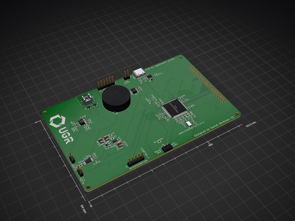
UGR Driver Screen 26 is an open-source printed circuit board by FRAG3RZ, from the FRAG3RZ/Engineering_Portfolio repository on GitHub. It is a 2-layer board of 133.5 × 84 mm with 76 parts on 130 nets, routed with 793 tracks and 233 vias.
It is built around the LM358DT, TPS562200DDC and AYZ0102AGRLC, with the PXP4013/08P/PC among its other parts. Its parts include 8 capacitors, 6 resistors, 6 ICs, 6 diodes and 4 connectors. It belongs with the STM32 boards of this library.


4th Year MEng Electrical & Electronic Engineering · University of Glasgow




Selected engineering projects spanning embedded firmware, custom electronics, PCB and schematic design, sensing, communications, testing, and hardware/software integration.
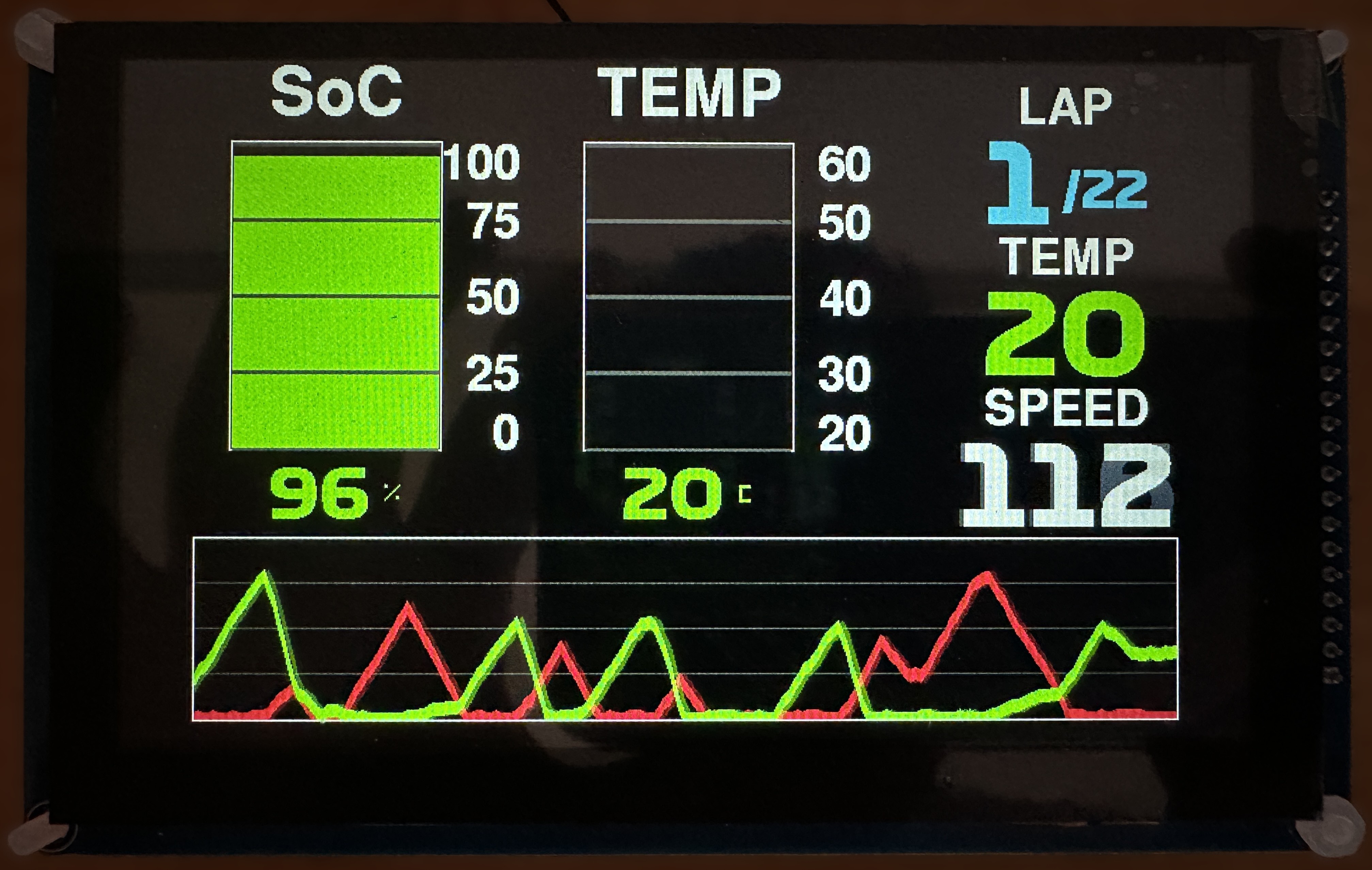



Custom embedded driver display developed for UGRacing Formula Student, combining a custom SMD PCB, STM32F767 firmware, CAN communications, an 800×480 touchscreen, and a purpose-built graphics/UI stack.
The published PCB revision was developed in KiCad, with subsequent redesign work carried out in Altium Designer.
My role: PCB and schematic design · SMD assembly · board bring-up · embedded C · display firmware · dashboard modes · CAN · touchscreen · hardware/software integration
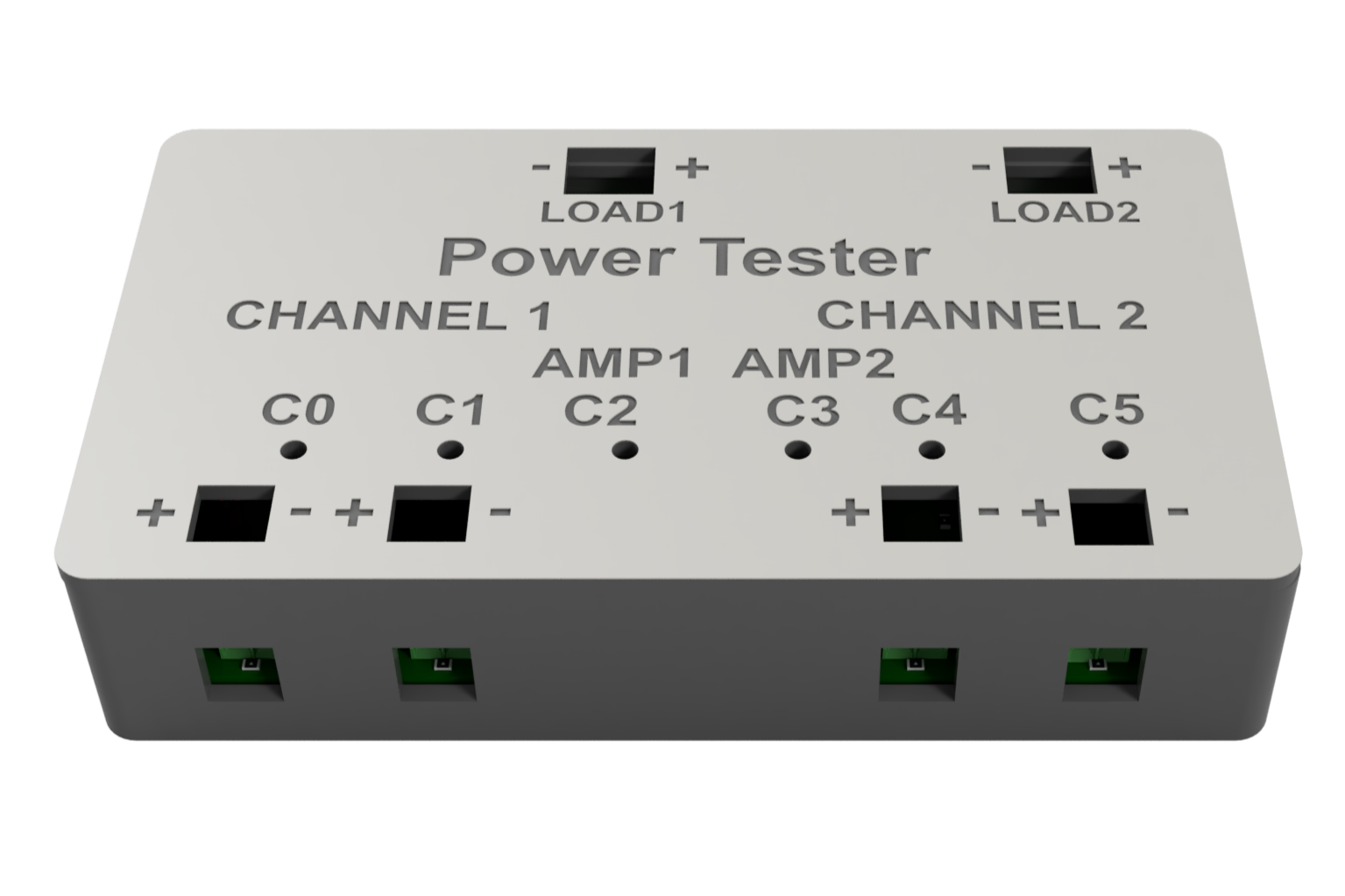





Custom automated test platform combining an FT232H-controlled PCB, multi-point voltage/current monitoring, switched and programmable MOSFET loads, Python automation and analysis, and a purpose-built 3D-printed enclosure with visual output indication.
My role: schematic & PCB design · Python automation · data analysis · FT232H interfacing · power measurement · programmable loads · 3D CAD & printing
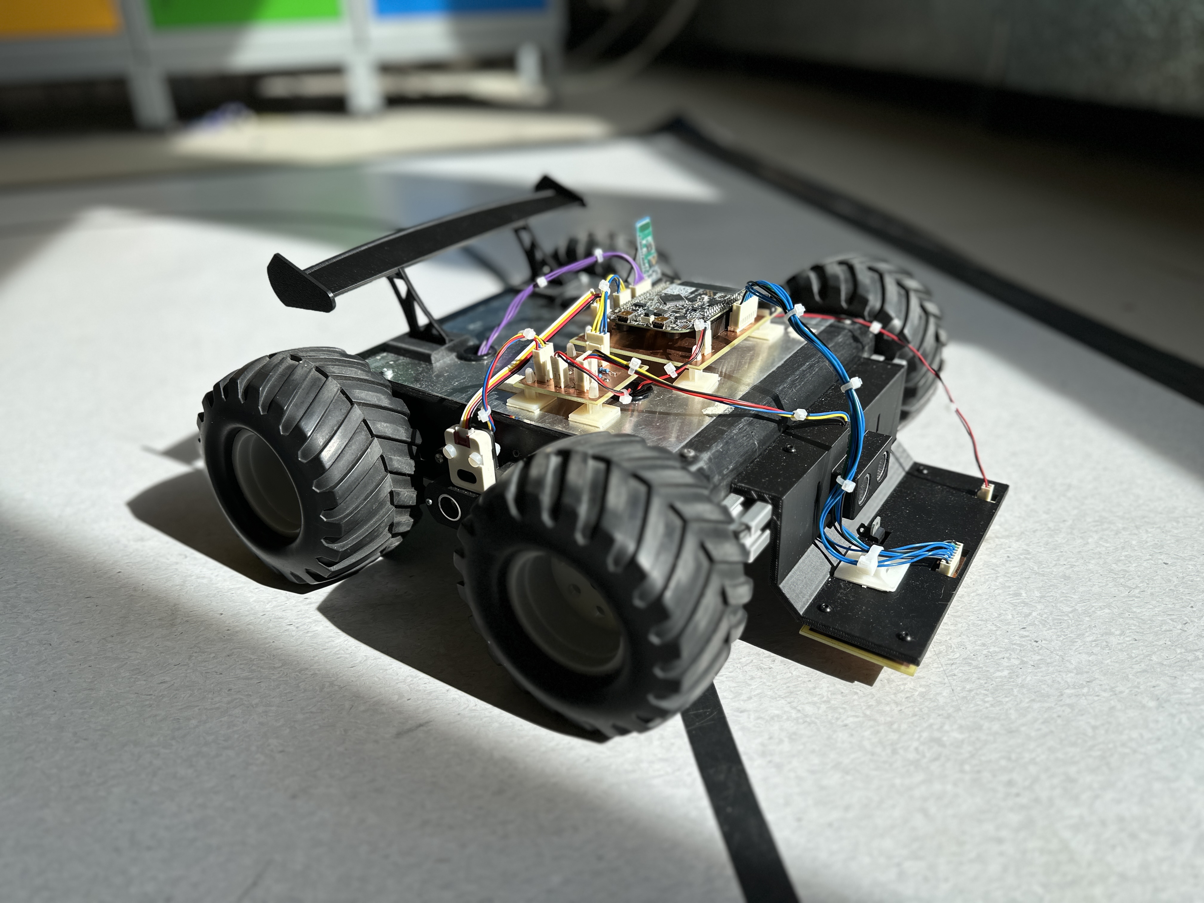



Autonomous embedded rover combining real-time C++ control, line sensing, ultrasonic ranging, colour detection, Bluetooth communication, motor control, and system-level integration.
My role: Team lead · embedded C++ · control architecture · motor and line-sensing electronics · subsystem integration
| Area | Technologies |
|---|---|
| Programming & Digital | C · C++ · Python · VHDL · STM32 · Git |
| Hardware | Altium Designer · PCB & Schematic Design · SMD Assembly · Oscilloscope · 3D Printing |
| Embedded Systems | CAN · I²C · SPI · USB · parallel display interfaces · hardware/software integration |
I am a penultimate-year MEng Electrical & Electronic Engineering student at the University of Glasgow, focused on embedded systems, digital hardware, PCB design, and low-level software.
My experience spans embedded firmware, PCB and schematic design, automated hardware testing, hardware debugging, and end-to-end hardware/software integration.

| Qty | Value | Footprint | References |
|---|---|---|---|
| 16 | 0.1u | Capacitor_SMD:C_0603_1608Metric_Pad1.08x0.95mm_HandSolder | C_NRST1, C_SD1, C_TPS1, C_TPS2, C_TPS3, C_VREF1, C1_VDD1, C2_VDD1, C3_VDD1, C4_VDD1, C5_VDD1, C6_VD1, C8_VDDA1, C12_U1, C14_U1, C20_U4 |
| 9 | 10k | Resistor_SMD:R_0603_1608Metric_Pad0.98x0.95mm_HandSolder | R_SD1, R_SD2, R_SD5, R_SD6, R1_BOOT0, R1_NRST1, R2_VBUS1, R5_U1, R11_U1 |
| 4 | 250 | Resistor_SMD:R_0603_1608Metric_Pad0.98x0.95mm_HandSolder | R_LED1, R_LED2, R_LED3, R_LIM1 |
| 4 | MountingHole_3.2mm_M3 | MountingHole:MountingHole_3.2mm_M3 | MH_3.2mm, MH_3.2mm, MH_3.2mm, MH_3.2mm |
| 3 | LED | Connector_PinHeader_2.54mm:PinHeader_1x02_P2.54mm_Vertical | D2, D3, D4 |
| 2 | 0.75A | Fuse:Fuse_1812_4532Metric_Pad1.30x3.40mm_HandSolder | F2, F3 |
| 2 | 10p | Capacitor_SMD:C_0603_1608Metric_Pad1.08x0.95mm_HandSolder | C1_OSC1, C2_OSC1 |
| 2 | 2.2u | Capacitor_SMD:C_0603_1608Metric_Pad1.08x0.95mm_HandSolder | C1_CAP1, C2_CAP1 |
| 2 | 22u | Capacitor_SMD:C_1210_3225Metric_Pad1.33x2.70mm_HandSolder | C16_U1, C18_U1 |
| 2 | 30k | Resistor_SMD:R_0603_1608Metric_Pad0.98x0.95mm_HandSolder | R_SD3, R_SD4 |
| 2 | 4.7k | Resistor_SMD:R_0603_1608Metric_Pad0.98x0.95mm_HandSolder | R1_I2C1, R2_I2C1 |
| 2 | 5.1k | Resistor_SMD:R_0603_1608Metric_Pad0.98x0.95mm_HandSolder | R1_CC1, R2_CC1 |
| 2 | ~ | MMBT5551LT1G:SOT95P237X111-3N | U4, U6 |
| 1 | 1.0u | Capacitor_SMD:C_0603_1608Metric_Pad1.08x0.95mm_HandSolder | C9_VDDA1 |
| 1 | 100k | Resistor_SMD:R_0603_1608Metric_Pad0.98x0.95mm_HandSolder | R_DISCH1 |
| 1 | 15u | Capacitor_SMD:C_1210_3225Metric_Pad1.33x2.70mm_HandSolder | C10_U1 |
| 1 | 20k | Resistor_SMD:R_0603_1608Metric_Pad0.98x0.95mm_HandSolder | R1_VBUS1 |
| 1 | 2171790001 | UGR:MOLEX_2171790001 | USB_C |
| 1 | 33.2k | Resistor_SMD:R_0603_1608Metric_Pad0.98x0.95mm_HandSolder | R10_U1 |
| 1 | 4.7u | Inductor_SMD:L_1206_3216Metric_Pad1.42x1.75mm_HandSolder | L2_U1 |
| 1 | AYZ0102AGRLC | AYZ0102AGRLC:SW_AYZ0102AGRLC | S1 |
| 1 | BZX384x | Diode_SMD:D_SOD-323 | D5 |
| 1 | BZX384xxxx | Diode_SMD:D_SOD-323 | D7 |
| 1 | CAN_TVS | Package_TO_SOT_SMD:SOT-23 | D1 |
| 1 | Conn_01x05 | Connector_PinHeader_2.54mm:PinHeader_1x05_P2.54mm_Vertical | J2 |
| 1 | Conn_01x06 | Connector_PinHeader_2.54mm:PinHeader_1x06_P2.54mm_Vertical | J5 |
| 1 | Conn_02x20_Socket | Connector_PinSocket_2.54mm:PinSocket_2x20_P2.54mm_Vertical | J3 |
| 1 | Crystal_GND24 | Crystal:Crystal_SMD_Abracon_ABM3B-4Pin_5.0x3.2mm | ABM3-8.000MHZ-10-1-U-T1 |
| 1 | DF51-4DP-2DS_50_ | DF51:HIROSE_DF51-4DP-2DS_50_ | J4 |
| 1 | LM358DT | LM358:SOIC127P600X175-8N | U3 |
| 1 | LOGO | Library:UGR_ALL_SILK_50mm | G*** |
| 1 | LOGO | UGR:UGR_ALL_SILK_30mm | G*** |
| 1 | MCP2562-E-SN | Package_SO:SOIC-8_3.9x4.9mm_P1.27mm | U5 |
| 1 | PXP4013/08P/PC | Apps:Bulgin_4000_PXP4013-08S-PC | CONN1 |
| 1 | STM32F767VGTx | Package_QFP:LQFP-100_14x14mm_P0.5mm | U2 |
| 1 | TPS562200 | Package_TO_SOT_SMD:SOT-23-6 | U1 |
| 1 | ~ | UGR:SOP65P640X120-8N | TPS2112APW1 |


UofTPhyEssSW/Student-Workshop-Course-L1
University of Toronto, Dept. of Physics, Electronic Support Services - Student Workshop Course L1 course files

esl-epfl/GSR_monitor
Discrete validation platform for the HEEPidermis low-power SoC, designed for low-noise Galvanic Skin Response (GSR) measurements


maurer-lbb/inkube_hardware
Open-source hardware (CAD + PCB) for inkudock, a modular incubator and closed-loop electrophysiology, and a water compartment lid preventing evaporation from cell cultures.
It measures 133.5 × 84 mm and has 2 copper layers, 1.6 mm thick.
76 parts, built around the LM358DT, TPS562200DDC, AYZ0102AGRLC and PXP4013/08P/PC. The full list of its parts is on this page, with links to each part's symbol and footprint where PCBKit's library has them.
From the FRAG3RZ/Engineering_Portfolio repository on GitHub, at the commit this page was made from: the board is Formula-Student-Driver-Display/Hardware/UGR_Driver_Screen_26.kicad_pcb and its schematic Formula-Student-Driver-Display/Hardware/UGR_Driver_Screen_26.kicad_sch. PCBKit opens the board in the browser, with nothing to install.
Its repository states no licence, so its author keeps all rights: ask FRAG3RZ before reusing the design.