
2 layers290.1 × 130 mm

 UAA-F14/ComplexCalc-HW
Standalone embedded complex n×n linear system solver (Gauss-Jordan, 2x2-4x4) on a custom STM32F411 PCB with a 4x4 keypad and ILI9341 TFT — no PC required
ComplexCalc is an open-source printed circuit board by UAA-F14, from the UAA-F14/ComplexCalc-HW repository on GitHub. It is a 2-layer board of 97.2 × 112.7 mm with 50 parts on 56 nets, routed with 736 tracks and 33 vias.
It is built around the AMS1117-3.3. Its parts include 25 switches, 10 capacitors, 6 resistors, 5 connectors and 2 ICs. It belongs with the STM32 boards of this library.
A standalone embedded calculator for complex n×n linear systems (Ax=b) — no PC required at runtime. Custom STM32F411 PCB with a 16-button keypad and an ILI9341 TFT display, built for electronics students and AC circuit analysis.
[!NOTE] Work in progress. Firmware is functional (keypad input, TFT UI, Gauss-Jordan solver); the PCB is still being routed (some ADC connections are pending — see Design).
├── code/
│   └── 06ComplexCalcDasProject/   # STM32CubeIDE / CMake firmware project
│       ├── Core/
│       │   ├── Inc/               # ComplexGJ.h (solver), TFT_Screen.h, display_ui.h, ...
│       │   └── Src/                # SWComplexGJ.c (solver), TFT_Screen.c, display_ui.c, main.c, ...
│       └── Drivers/                # Vendored STM32 HAL + CMSIS (ST-generated, not project code)
├── design/
│   └── ComplexCalc/                # KiCad schematic + PCB (in progress)
└── README.md
The actual project logic lives in Core/Inc / Core/Src; everything under Drivers/ is STM32CubeMX-generated boilerplate.
float) complex arithmetic, systems from 2×2 up to 4×4.No serial terminal, USB host, or PC connection is needed to use the calculator — power it on, and the keypad + screen are the whole interface. (USB/SWD is only used to flash firmware.)
Using STM32CubeIDE (recommended):
code/06ComplexCalcDasProject/.Ctrl+B), then flash over USB/SWD (Ctrl+Alt+X).Using CMake + the ARM GCC toolchain (also supported by this project):
cd code/06ComplexCalcDasProject
cmake --preset Debug      # or: Release
cmake --build --build-preset Debug
This uses the project's own cmake/gcc-arm-none-eabi.cmake toolchain file — you'll need arm-none-eabi-gcc and ninja installed.
On power-up, the screen prompts for the system size (2–4). From there:
| Input | Action |
|---|---|
0–9 | Enter digits (toggles between real/imaginary part) |
= | Confirm entry / advance |
S + P (combo) | Cycle display theme |
Once the full A matrix and b vector are entered, the solver runs on-device and the result is shown on screen — no PC needed.
solve_complex_system in ComplexGJ.h/SWComplexGJ.c).EPSILON = 1e-7 for singularity checks.N_MAX), matching the keypad-driven size range (2–4).SOLVER_ERR_INVALID_SIZE / SOLVER_ERR_SINGULAR for out-of-range sizes or singular matrices.KiCad project at design/ComplexCalc/ — schematic + PCB for the keypad, MCU, TFT header, and power circuitry.
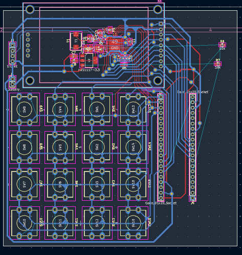
Routing in progress — some ADC-related connections are still pending. A rendered board image will replace this screenshot once the layout is finished.
A datasheet-vs-schematic power supply review (VCAP sizing, VBAT, NRST, HSE crystal value) is available at docs/ComplexCalc-HW_power_supply_review_en.pdf (Spanish version).
code/06ComplexCalcDasProject/Core/.design/ComplexCalc/ (KiCad 8+).Report bugs or hardware questions via this repo's Issues.
| Qty | Value | Footprint | References |
|---|---|---|---|
| 5 | 10k | Resistor_SMD:R_0805_2012Metric | R4, R5, R6, R7, R8 |
| 4 | 100nF | Capacitor_SMD:C_0805_2012Metric_Pad1.18x1.45mm_HandSolder | C9, C10, C11, C12 |
| 4 | MOD | Button_Switch_THT:SW_PUSH-12mm | SW18, SW20, SW26, SW28 |
| 2 | 22pF | Capacitor_SMD:C_0805_2012Metric_Pad1.18x1.45mm_HandSolder | C5, C6 |
| 2 | Conn_01x20_Socket | Connector_PinHeader_2.54mm:PinHeader_1x20_P2.54mm_Vertical | J4, J5 |
| 1 | - | Button_Switch_THT:SW_PUSH-12mm | SW10 |
| 1 | . | Button_Switch_THT:SW_PUSH-12mm | SW8 |
| 1 | 0 | Button_Switch_THT:SW_PUSH-12mm | SW9 |
| 1 | 1 | Button_Switch_THT:SW_PUSH-12mm | SW4 |
| 1 | 10uF | Capacitor_SMD:C_0805_2012Metric_Pad1.18x1.45mm_HandSolder | C7 |
| 1 | 1uF | Capacitor_SMD:C_0805_2012Metric | C13 |
| 1 | 2 | Button_Switch_THT:SW_PUSH-12mm | SW5 |
| 1 | 220 | Resistor_SMD:R_0805_2012Metric | R3 |
| 1 | 22uF | Capacitor_SMD:C_0805_2012Metric_Pad1.18x1.45mm_HandSolder | C8 |
| 1 | 3 | Button_Switch_THT:SW_PUSH-12mm | SW6 |
| 1 | 4 | Button_Switch_THT:SW_PUSH-12mm | SW1 |
| 1 | 4.7uF | Capacitor_SMD:C_0805_2012Metric_Pad1.18x1.45mm_HandSolder | C14 |
| 1 | 5 | Button_Switch_THT:SW_PUSH-12mm | SW2 |
| 1 | 6 | Button_Switch_THT:SW_PUSH-12mm | SW3 |
| 1 | 7 | Button_Switch_THT:SW_PUSH-12mm | SW13 |
| 1 | 8 | Button_Switch_THT:SW_PUSH-12mm | SW14 |
| 1 | 8MHz | Crystal:Crystal_SMD_EuroQuartz_MQ2-2Pin_7.0x5.0mm | Y1 |
| 1 | 9 | Button_Switch_THT:SW_PUSH-12mm | SW15 |
| 1 | < | Button_Switch_THT:SW_PUSH-12mm | SW19 |
| 1 | <- | Button_Switch_THT:SW_PUSH-12mm | SW12 |
| 1 | = | Button_Switch_THT:SW_PUSH-12mm | SW7 |
| 1 | > | Button_Switch_THT:SW_PUSH-12mm | SW27 |
| 1 | AMS1117-3.3 | Package_TO_SOT_SMD:SOT-223-3_TabPin2 | U2 |
| 1 | Conn_01x09 | Display:CR2013-MI2120 | J2 |
| 1 | LED | LED_SMD:LED_0603_1608Metric | D1 |
| 1 | M | Button_Switch_THT:SW_PUSH-12mm | SW16 |
| 1 | OK | Button_Switch_THT:SW_PUSH-12mm | SW23 |
| 1 | STLINK | Connector_PinHeader_2.54mm:PinHeader_1x04_P2.54mm_Vertical | J3 |
| 1 | STM32F411CEUx | Package_DFN_QFN:QFN-48-1EP_7x7mm_P0.5mm_EP5.6x5.6mm | U3 |
| 1 | V_Battery | Connector_PinHeader_2.54mm:PinHeader_1x02_P2.54mm_Vertical | J1 |
| 1 | ^ | Button_Switch_THT:SW_PUSH-12mm | SW22 |
| 1 | del | Button_Switch_THT:SW_PUSH-12mm | SW11 |
| 1 | v | Button_Switch_THT:SW_PUSH-12mm | SW24 |

pascallanger/DIY-Multiprotocol-TX-Module
Multiprotocol TX Module (or MULTI-Module) is a 2.4GHz transmitter module which controls many different receivers and models.

fossasia/pslab-hardware
PSLab Hardware Design and Schematics https://pslab.io


MaltWhiskey/Mega-Cube
16x16x16 PL9823 Cube with Teensy 4.0 and FlexIO driver


shamansystems/Cheap-FOCer-2
Low-Cost Motor Controller based on the VESC 6
It measures 97.2 × 112.7 mm and has 2 copper layers, 1.6 mm thick.
50 parts, built around the AMS1117-3.3. The full list of its parts is on this page, with links to each part's symbol and footprint where PCBKit's library has them.
From the UAA-F14/ComplexCalc-HW repository on GitHub, at the commit this page was made from: the board is design/ComplexCalc/ComplexCalc.kicad_pcb and its schematic design/ComplexCalc/ComplexCalc.kicad_sch. PCBKit opens the board in the browser, with nothing to install.
Its repository states no licence, so its author keeps all rights: ask UAA-F14 before reusing the design.