2 layers55 × 79 mm
Tympan nRF52 Programmer
Tympan/Tympan_Rev_F_Hardware
Tympan Rev F Hardware Design Files
8 parts7CERN-OHL-P-2.0

 Tympan/Tympan_Rev_F_Hardware7
Tympan Rev F Hardware Design Files
Tympan Rev F is an open-source printed circuit board by Tympan, from the Tympan/Tympan_Rev_F_Hardware repository on GitHub, published under the CERN-OHL-P-2.0 licence. It is a 4-layer board of 38 × 74 mm with 91 parts on 142 nets, routed with 942 tracks and 163 vias.
It is built around the MDBT50Q-1MV2, TEENSY 4.1 and TLV320AIC3206IRSBT, with the 74LVC1G66GW, LP5907MFX-1.8 and MCP73831 among its other parts. Its parts include 28 capacitors, 28 resistors, 12 connectors, 7 ICs and 4 diodes. It belongs with the nRF52 and nRF5x and NXP (LPC, Kinetis, i.MX RT) boards of this library.


Tympan Rev F Hardware Design Files For First Production Run, Februrary, 2024.
Tympan is Certified Open Source Hardware!

For the most part, the design of Rev F is a clone of Rev E. The primary challenge of producing Rev E is that the BC127 BLE Radio module we used is not longer available (Product End Of Life). Here are the major changes in the hardware
Like all previous Tympan revisions, the Rev F has expansion headers to allow the addition of add-on boards, such as the Tympan AIC shield. The pinout for the expansion headers is identical for Rev F as for previous Tympan revisions. The pinout is shown in the schematic as headers P1 through P4. You can also see the pinout below.
Any updates to the application software can be done over Bluetooth using Over The Air Device Firmware Update (OTA DFU). This tutorial will use Adafruit's Bluefruit Connect app, which is available for iPhone and Android.

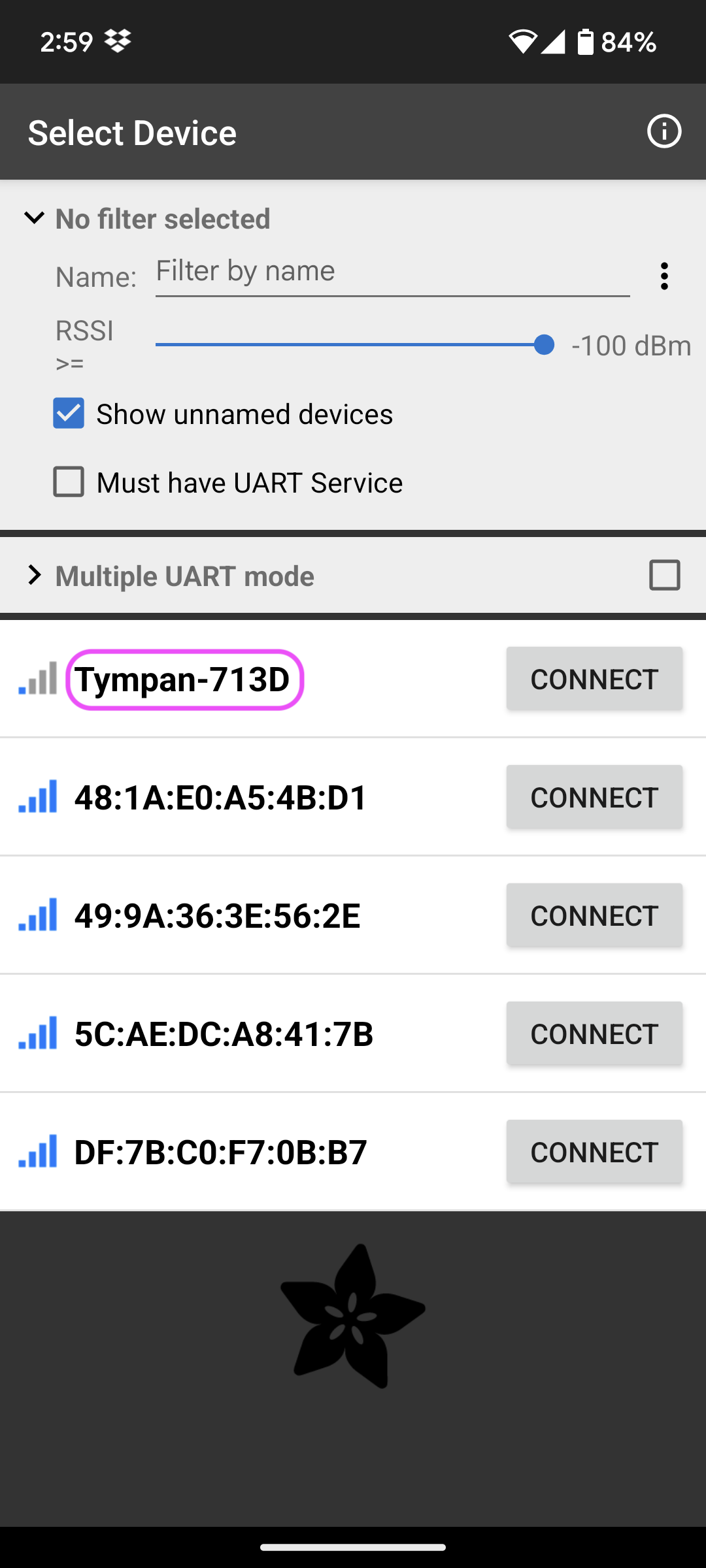
You will also need two files to upload which Arduino makes when. One is the .hex file, The other is a .dat file. The latest version of our Tympan Radio firmware is published as a release on this repository, which you can download HERE The link will take you to the latest release of the firmware. Download the .ZIP file that is linked there. Both of these files need to be accessible on the phone, or tablet, that you intend to use to perform the OTA DFU. When you have the files on your mobile device, open up the Bluefruit App, and connect to the Tympan that you want to update. Each Tympan advertises it's name followed by a unique ID. Click on connect.
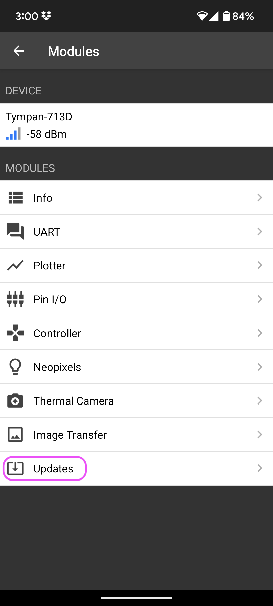
After connecting, the app will show you various tools. Scroll to the bottom and select the Updates tool.
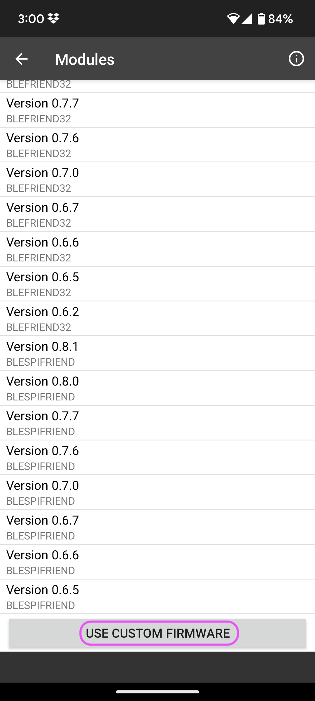
There is a long list of updates that are for Adafruit's BLE products. Scroll all the way to the bottom and select Custom Firmware.
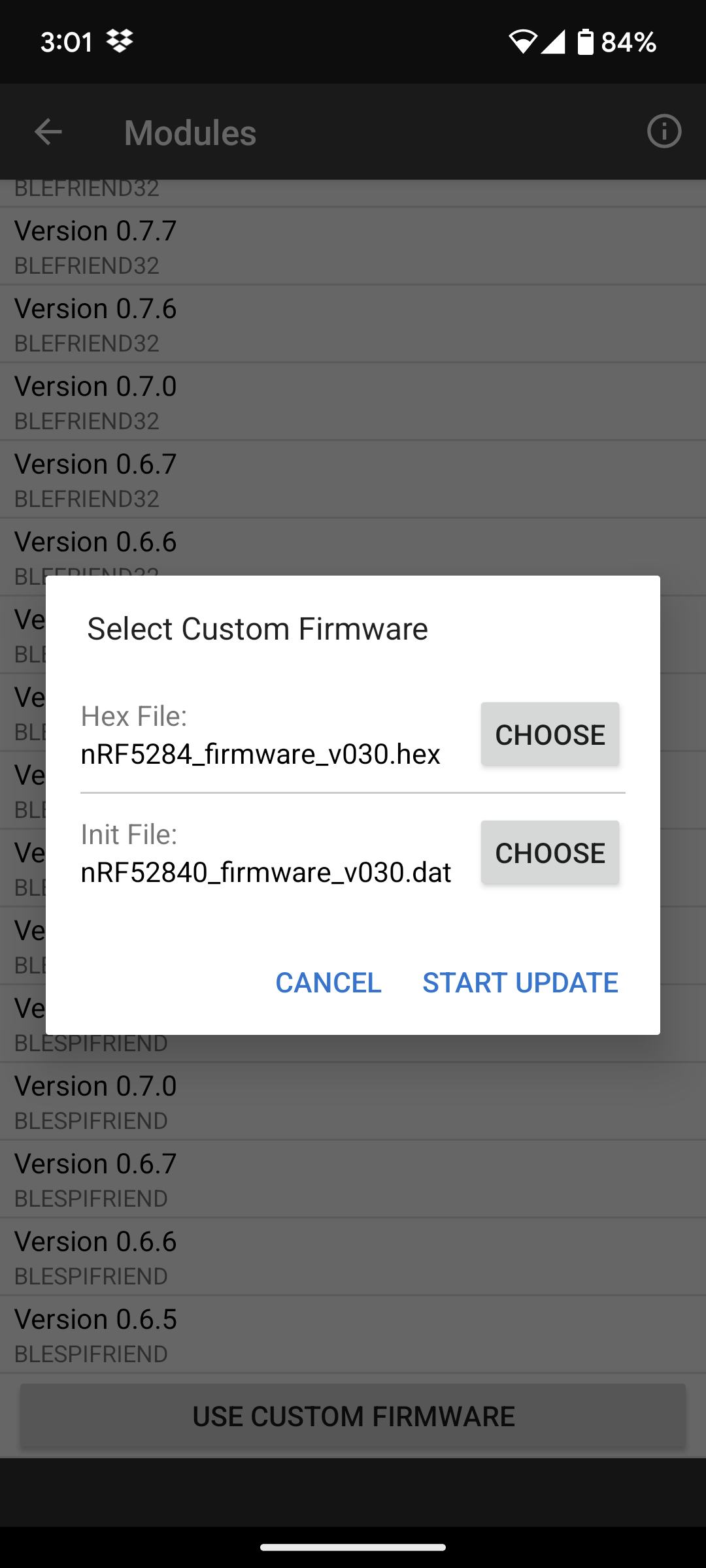
The pop-up window will ask you to choose the Hex and Init files. Navigate to the place where you have stored the files you downloaded from our latest release. Choose our hex file for the .hex, and our dat file for the Init file. When you press START UPDATE, the process will begin, and the upload will show a progress bar.
That's it! After successful upload, your Tympan Radio will be running the latest and greatest firmware version. If you want to continue to use the Bluefruit App, it is advised to close the close it after the upload process is complete, and then restart if you intend to use it again right away.
NOTE: This method is included here for completion. OTA DFU should suffice of all updates
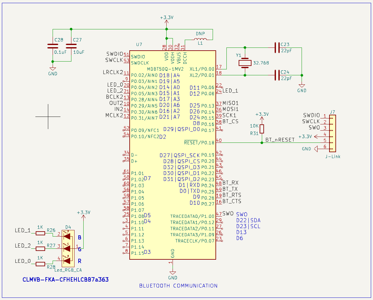
The blank nRF52 module is programmable using the j-Link connection on pins SWO, SWCLK, SWDIO, RESET, 3V3, and GND. Those module pins are broken out to a header row on the bottom of the board. See connector J7 in the schematic, and the 6 SMT pads on the back layer of the PCB design.
 -
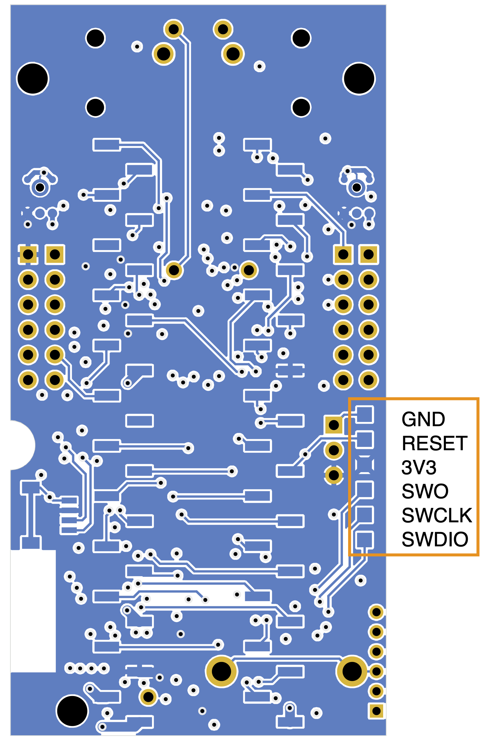
We have a specific PCB card for bootloading and programming the nRF52 The folder called Tympan nRF52 Programmer contains design files for this PCB. This PCB is not 100% necessary for bootloading and programming the radio. As long as you make the correct connections between the J-Link programmer and the 6 pads on the bottom of the board, you will have success using the How To Program instructions below.
The J-Link by Segger is preferred for flashing the bootloader and any application layer onto the nRF52. You can get one from various suppliers. Adafruit, Mouser, Digikey all carry them.
Adafruit also sells a low-cost J-Link for educational purposes. The EDU version is specifically not for use in commercial applications. If you need to re-program your radio from the bootloader up, your personal use of the EDU version will not break that rule!
There are a couple of routes through different toolchains that are available to bootload the nRF52 module using the J-link. Our current method uses Command Line Tools from Nordic, the makers of the nRF52 chipset. Download the Command Line Tools, and install them to Program Files (x86). You will also need one element of the Adafruit nRF52 toolset, which means that you need to install it through the Arduino IDE, as described in the section below "Compiling the Firmware".
>>> NOTE: This tutorial currently only supports Windows OS
The other software that you need is Arduino IDE, which is assumed to be installed and updated to the latest version. Arduino will very tidily create the proper compiled files for flashing. Click on Sketch > Export Compiled Binary and the IDE will create a folder called build inside your Sketch folder. The build folder contains a subfolder specific to the board. Click on Sketch > Show Sketch Folder to open it in an explore window. Inside the subfolder you will find 4 files.
Each file is used for different Device Firmware Update (DFU) processes. For the purpose of initial flashing via J-Link, we will use the .hex file. You may note that the full name of the file is something like TympanRadio_baseFirmware.ino.hex. The inclusion of the .ino in the name should not cause a problem, but if you want you can change the name and remove the .ino. Just make sure to keep the .hex suffix.
We will be flashing a blank nRF52 module with Adafruit's Feather Express bootloader variant. The file we need is a .hex file, and it is located in C:\Users\{USERNAME}\AppData\Local\Arduino15\packages\adafruit\hardware\nrf52\1.6.0\bootloader\feather_nrf52840_express\feather_nrf52840_express_bootloader-0.8.0_s140.6.1.1.hex. We recommend making a copy of it, and moving it into the same folder that the IDE just made to keep things tidy.
Open a Command Prompt window, and navigate to C:\Program Files (x86)\Nordic Semiconductor\nrf-command-line-tools\bin, and then enter the following commands:
nrfjprog --program {PATH}\feather_nrf52840_express_bootloader-0.8.0_s140_6.1.1.hex --format NRF52 --chiperase --reset && nrfjprog --memwr 0xFF000 --val 0x01 && nrfjprog --reset --program {PATH}\TympanRadio_baseFirmware.ino.hex --sectorerase --format NRF52 --verify --log
The first command flashes the bootloader and the Bluetooth soft device. The second command sets a bit in 0xFF000 in order to bypass 'virgin program' hurdle. The third command programs the application software.
Ideally, you do not need to compile the firmware; you would just use the pre-compiled HEX file already included with this repository. But, if you do need to re-compile:
Once everything is installed, use the Arduino IDE to open "nRF52840_firmware.ino" that is here in the Tympan Rev F repository. You need to tell the Arduino IDE what hardware you are programming for:
Now you can make any changes you want to the code. When done, compile. The Arduino IDE cannot upload the firmware directly to the nRF58240 in the Tympan. Instead, you must use the "hardware connection" or "over the air" methods described in the sections above. To get the HEX and DAT files for these methods:
| Qty | Value | Footprint | References |
|---|---|---|---|
| 8 | 0.1uF | Capacitor_SMD:C_0402_1005Metric | C6, C8, C10, C13, C17, C18, C25, C28 |
| 8 | 2.2uF | Capacitor_SMD:C_0402_1005Metric | C1, C2, C3, C4, C5, C11, C15, C16 |
| 8 | 33R | Resistor_SMD:R_0402_1005Metric | R3, R4, R5, R6, R7, R8, R9, R10 |
| 6 | 1uF | Capacitor_SMD:C_0402_1005Metric | C12, C19, C20, C21, C22, C26 |
| 5 | 1K | Resistor_SMD:R_0402_1005Metric | R1, R11, R26, R27, R28 |
| 4 | 10uF | Capacitor_SMD:C_0402_1005Metric | C7, C9, C14, C27 |
| 4 | 4K7 | Resistor_SMD:R_0402_1005Metric | R29, R30, R32, R33 |
| 4 | CONN_01X06 | Connector_PinHeader_2.54mm:PinHeader_1x06_P2.54mm_Vertical | P1, P2, P3, P4 |
| 3 | CONN_01X01 | MountingHole:MountingHole_3mm | P6, P7, P8 |
| 3 | DNP | Resistor_SMD:R_0603_1608Metric | R2, R16, R17 |
| 2 | 0R | Resistor_SMD:R_0603_1608Metric | R13, R14 |
| 2 | 2.2K | Resistor_SMD:R_0603_1608Metric | R15, R18 |
| 2 | 22pF | Capacitor_SMD:C_0402_1005Metric | C23, C24 |
| 2 | 240R | Resistor_SMD:R_0402_1005Metric | R19, R20 |
| 2 | LED | Capacitor_SMD:C_1206_3216Metric | D2, D3 |
| 2 | SPM0687LR5H-1 | Tympan:SPM0687LR5H-1 | MIC1, MIC2 |
| 1 | 10K | Resistor_SMD:R_0402_1005Metric | R31 |
| 1 | 2.2K | Resistor_SMD:R_0402_1005Metric | R12 |
| 1 | 32.768 | Tympan:XTAL | Y1 |
| 1 | 4UCON-20519 | Solutions:4UCON-0217-20519 | BT2 |
| 1 | 74LVC1G66 | Package_TO_SOT_SMD:SOT-353_SC-70-5 | U3 |
| 1 | APHB1608SGNC | Tympan:ABHB1608S | D1 |
| 1 | Battery_Cell | Battery:BatteryHolder_Keystone_3001_1x12mm | BT1 |
| 1 | CL-SB-22A | Tympan:CL-SB-22A | SW1 |
| 1 | Conn_01x06 | Pin_Headers:Pin_Header_Straight_1x06_Pitch2.00mm | J3 |
| 1 | DNP | Capacitor_SMD:C_0603_1608Metric | L1 |
| 1 | FUSE | Capacitor_SMD:C_1206_3216Metric | F1 |
| 1 | J-Link | Solutions:J-Link_SMT_SIP_0.1inP | J7 |
| 1 | LC709203 | Tympan:WDFN8_3X4mm_0.65P | U6 |
| 1 | LOGO | Solutions:Tympan_LOGO | G*** |
| 1 | LOGO | Solutions:oshwa-logo-gear | G*** |
| 1 | LP5907MFX-1.8 | Package_TO_SOT_SMD:SOT-23-5 | U4 |
| 1 | Led_RGB_CA | Solutions:CLMVB-FKA-CFHEHLCBB7a363 | D4 |
| 1 | MCP73831 | Package_TO_SOT_SMD:SOT-23-5 | U1 |
| 1 | MDBT50Q-1MV2 | RF_Module:Raytac_MDBT50Q | U7 |
| 1 | POT | Connector_PinHeader_2.54mm:PinHeader_1x03_P2.54mm_Vertical | RV1 |
| 1 | Qwiik Connector | Connectors_JST:JST_SH_SM04B-SRSS-TB_04x1.00mm_Angled | J4 |
| 1 | SJ-3523-SMT-TR | Tympan:SJ-3523-SMT-TR | J1 |
| 1 | SJ-3524-SMT-TR-PI | Tympan:SJ-3524-SMT-TR | J2 |
| 1 | SW_Push | Tympan:MJTP1117 | SW2 |
| 1 | TLV320AIC3206IRSBT | Package_DFN_QFN:UQFN-40-1EP_5x5mm_P0.4mm_EP3.8x3.8mm | U2 |
| 1 | Teensy4.1 | teensy:Teensy41_SMT | U5 |
Tympan/Tympan_Rev_F_Hardware
Tympan Rev F Hardware Design Files

Tympan/Tympan_Rev_E_Hardware
Repository for Tympan Rev E Electronics and case designs


Tympan/Tympan_AIC_Shield
Add a CODEC to your Tympan with this daughter card!


Tympan/Tympan_Earpiece_Shield
Shield for Tympan Rev D that supports Tympan BTE Hardware

martinroger/ipodesp32
An iPod emulator for 2006-2013 BMW Mini Coopers that need Bluetooth
It measures 38 × 74 mm and has 4 copper layers, 1.6 mm thick.
91 parts, built around the MDBT50Q-1MV2, TEENSY 4.1, TLV320AIC3206IRSBT and 74LVC1G66GW. The full list of its parts is on this page, with links to each part's symbol and footprint where PCBKit's library has them.
From the Tympan/Tympan_Rev_F_Hardware repository on GitHub, at the commit this page was made from: the board is Tympan_Rev_F/Tympan_Rev_F.kicad_pcb and its schematic Tympan nRF52 Programmer/Tympan nRF52 Programmer.kicad_sch. PCBKit opens the board in the browser, with nothing to install.
Its repository publishes it under the CERN-OHL-P-2.0 licence: you may reuse it on that licence's terms (keep the author's notice, and for a copyleft licence share your changes alike).