ESPHome controller for Dimplex ZL 300/400 VF ventilation units – isolated 24 V I/O, XIAO ESP32-C6, KiCad PCB, 3D-printed case. | ESPHome-Steuerung für Dimplex-Lüftungsgeräte ZL 300/400 VF mit Home Assistant.
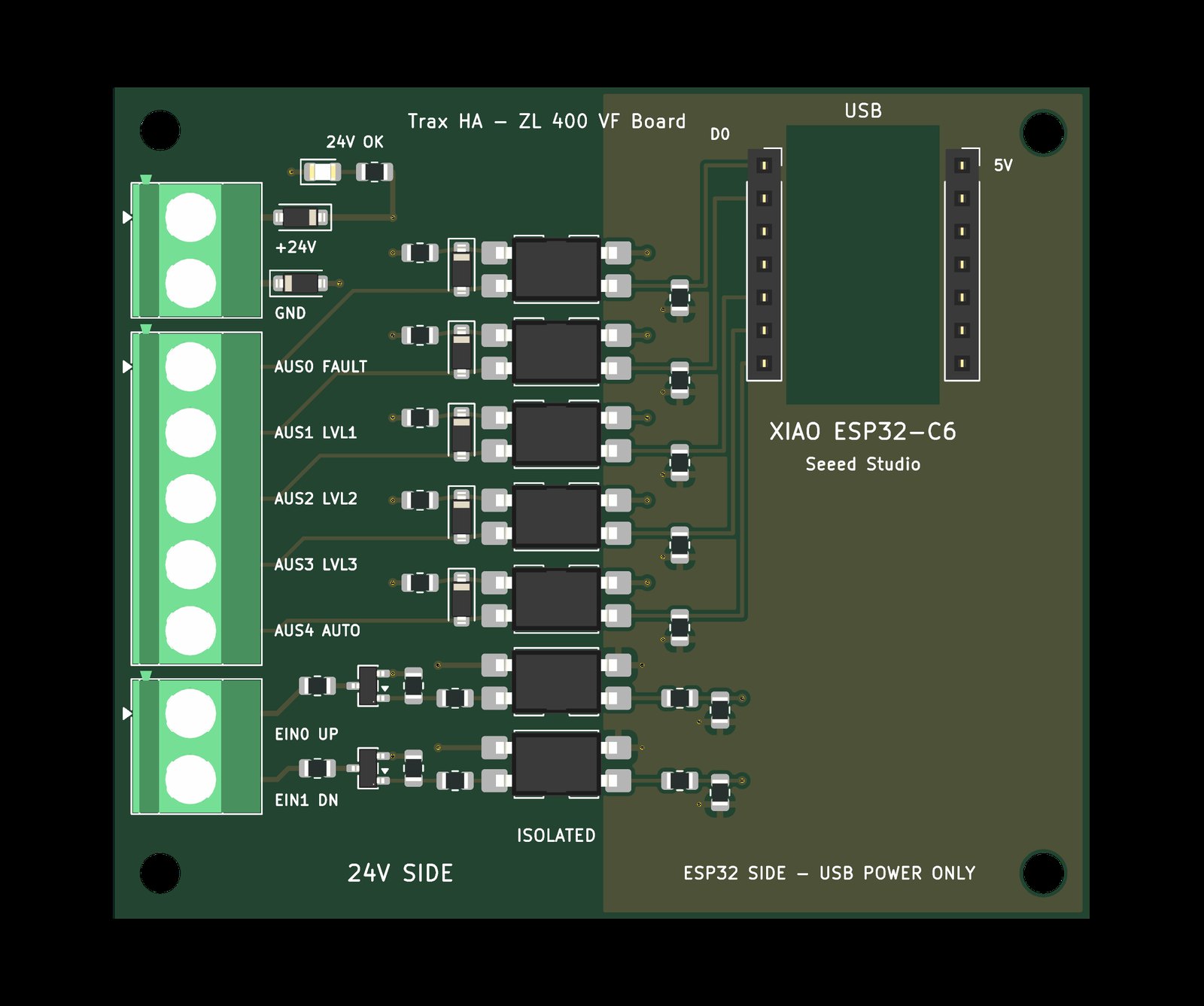
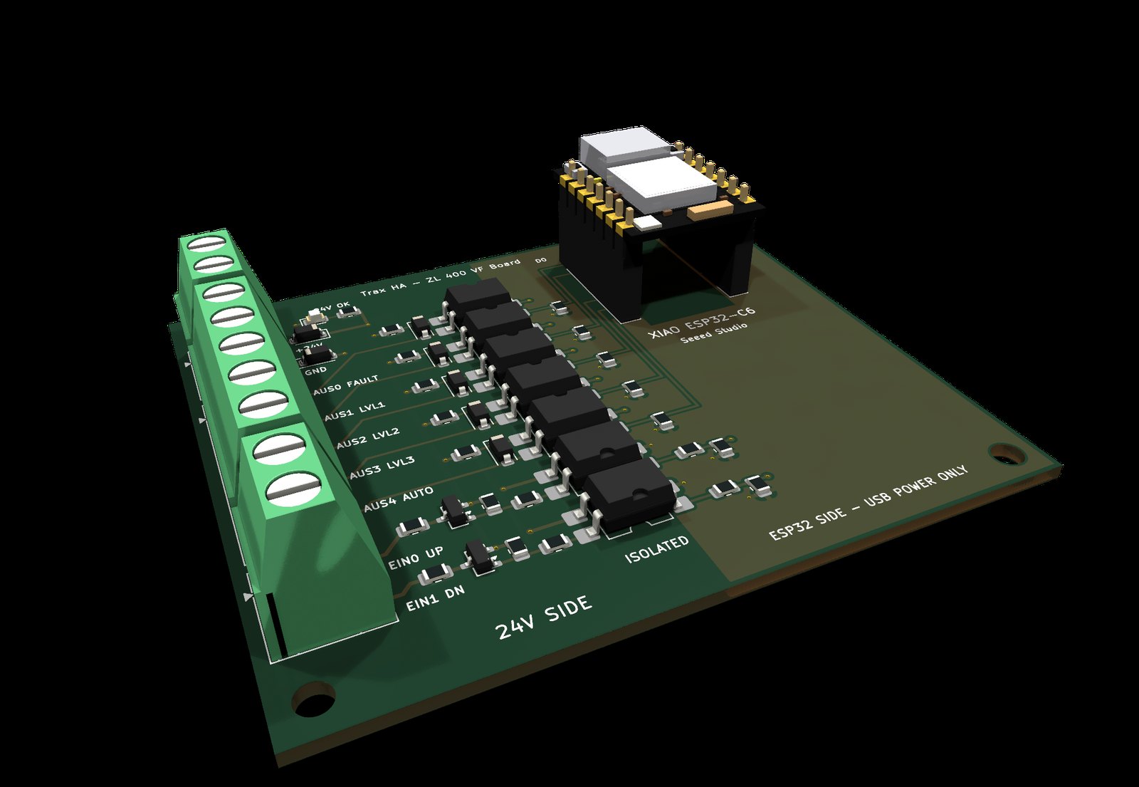
ESP24V HA XIAO is an open-source printed circuit board by Traxes, from the Traxes/dimplex-zl400-esphome repository on GitHub, published under the MIT licence. It is a 2-layer board of 75 × 64 mm with 47 parts on 39 nets, routed with 110 tracks and 28 vias.
It is built around the EL817-S1, 1N4148W and MMBT3906. Its parts include 21 resistors, 8 diodes, 7 ICs, 5 connectors and 2 transistors. It belongs with the home automation and IoT boards of this library.
[!TIP]
Want a ready-made one? I can build the assembled PCB and the 3D-printed enclosure for you – in any color, and the case can be adapted to your installation (shape, mounting, cable exits). If you're interested, open a request. Please don't post your address or phone number in the issue – details are arranged privately.
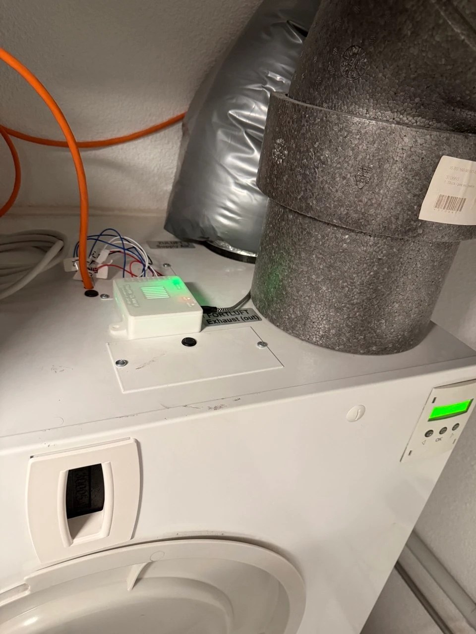
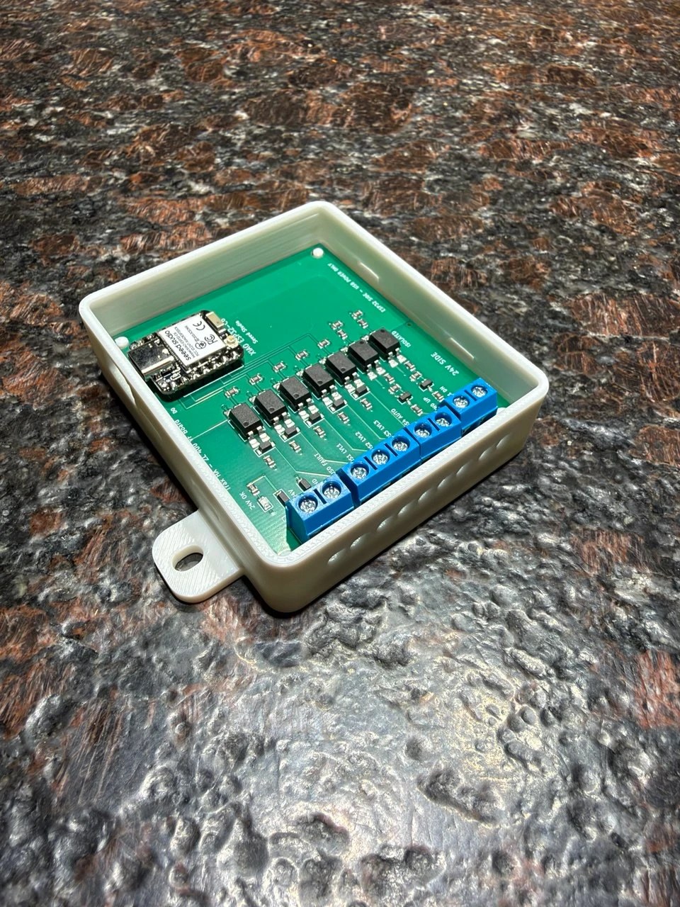
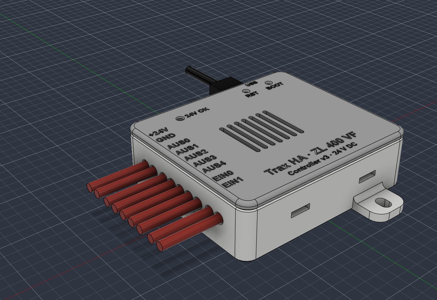
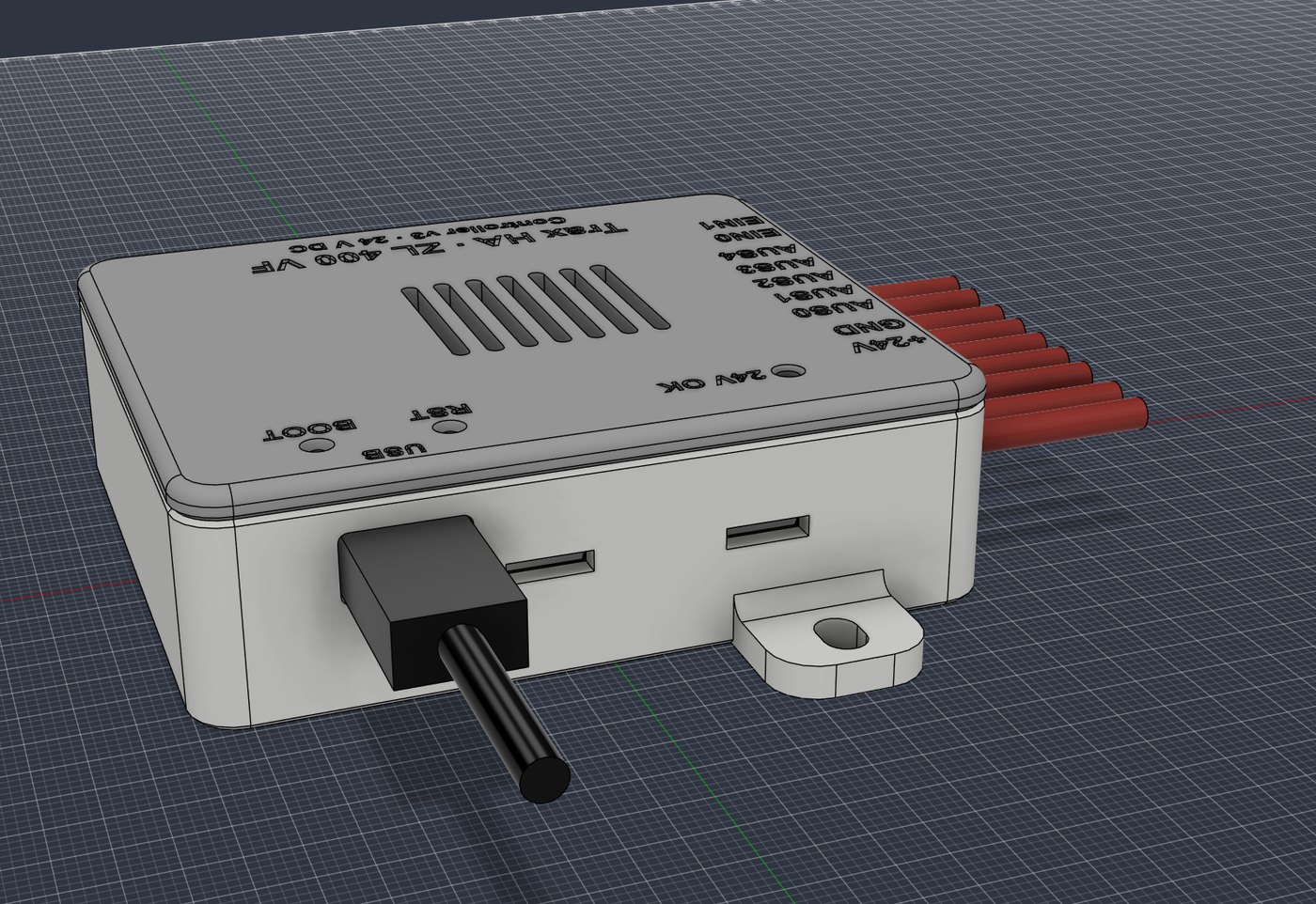
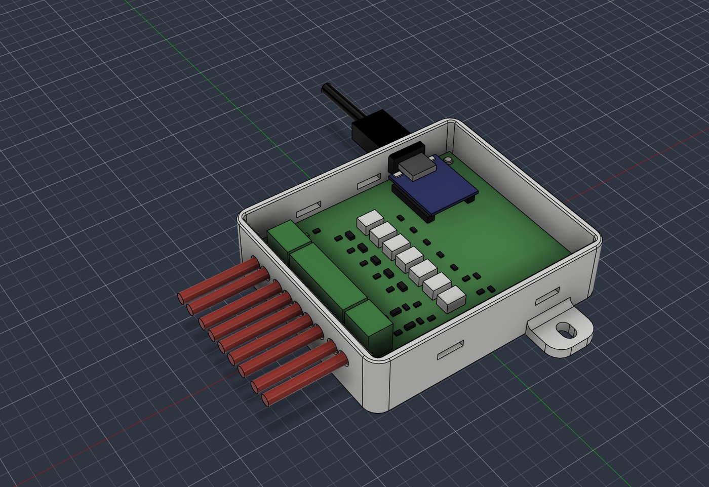
Left: installed on a ZL 400 VF, wires to the unit's terminal board. Right: controller v3 in the printed case (lid removed).
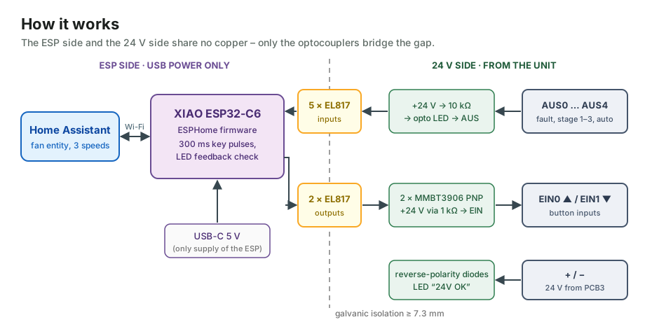
A drop-in replacement for the wall control panel (“Bedienelement Typ 1”) of Dimplex ZL 300 VF / ZL 400 VF home ventilation units. A Seeed XIAO ESP32-C6 reads the unit's five 24 V status outputs through optocouplers and “presses” the up/down buttons with optocoupler-driven PNP switches. In Home Assistant the unit shows up as a normal fan with three speeds.
Highlights
Galvanically isolated: the ESP is powered only by USB-C, nothing but optocouplers crosses to the unit's 24 V side.
Closed-loop control: every key press is verified through the unit's LED outputs; retries with back-off, fault entities for HA.
Snap-fit 3D-printed enclosure without screws, generated by a parametric Fusion 360 script.
Worst-case analysis, SPICE Monte Carlo and FMEA in docs/qa (German).
Status (2026-10-19): installed and running in a ZL 400 VF. Live test off → 1 → 3 → 2 → off: LED feedback within 3 s for every step, no fault flags.
[!WARNING]
The ventilation unit contains mains voltage (230 V). Read the safety notes before you open the unit or connect anything. Build at your own risk. This is not a Dimplex product.
Python scripts used for QA, simulation and fabrication checks
Safety
[!CAUTION]
Working on the ventilation unit can be life-threatening: there is mains voltage (230 V) inside. Read this section completely before you start.
Electrical
Before opening the unit or the terminal compartment, disconnect it from mains on all poles (circuit breaker or isolating switch). Secure it against being switched back on and verify that it is dead. Work on mains wiring is for qualified electricians only.
The controller is designed only for the unit's 24 V DC control circuit (PCB3 terminals +, −, AUS_x, EIN_x).
Never connect any terminal to mains or to another voltage source.
The absolute maximum is 30 V; above 27.5 V parts run outside their derating limits.
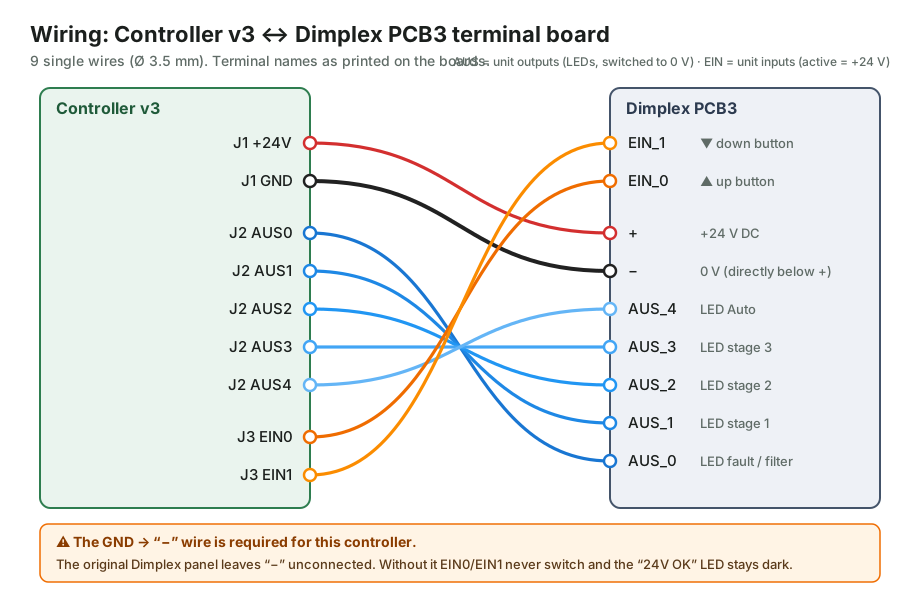
Measure + to − on PCB3 (DC volts) and check every wire against the wiring diagram before you connect the controller. Swapping + and − is blocked by diodes; other wiring mistakes are not.
Use ferrules on stranded wires, strip only as much as the terminal needs, and pull-test every wire. A stray strand can short the unit's 24 V supply.
Leave all other PCB3 terminals untouched. In particular, keep the RM (smoke detector) bridge in place: it is a safety shutdown input of the unit.
Do not connect other loads to the unit's 24 V supply. Its transformer is only rated for a few control panels and sensors (Dimplex manual, table 4.1).
ESP / USB side
Power the XIAO only from a certified USB power supply (safety extra-low voltage, CE marked). Never feed it from the unit's 24 V.
Never connect USB ground or any ESP pin to the unit's wiring. The isolation between the two sides must stay intact.
Enclosure and location
The printed enclosure is not flame-retardant: PLA and PETG are not UL 94 V-0. The controller dissipates only milliwatts, but keep it away from heat sources and out of the air stream of electric heater coils.
PLA softens from about 55 °C; use PETG or ASA for warm locations.
Install only in dry, frost-free rooms (the same requirements as for the unit itself): no condensation, no outdoor use.
Close the lid before operation; it protects the terminals against accidental contact.
Ventilation function
Home ventilation protects the building against moisture and mould. Make sure your automations can never keep the unit off for long periods, and keep the minimum ventilation required for your building (in Germany, for example, the moisture-protection level of DIN 1946-6).
If a fireplace or other combustion appliance shares the air volume, the safety devices required for that combination (for example a pressure monitor) stay mandatory. This controller does not replace them, and remote control must never override them.
The unit's own protective functions (frost protection, smoke-detector shutdown, filter alarm) stay active. Do not bypass them.
A Wi-Fi or firmware fault can leave the unit at its last stage. Watch control_failed and feedback_lost in Home Assistant; the unit's own display and buttons keep working as a fallback.
Liability
Building and using this is at your own risk. Connecting third-party electronics may affect the warranty of the ventilation unit. The documents come without any guarantee of correctness. This project is not affiliated with Dimplex.
How it works
Direction
Circuit
Unit → ESP (AUS0–AUS4)
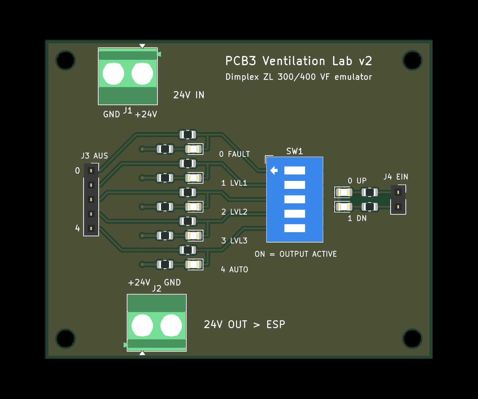
+24 V → 10 kΩ → EL817 LED → AUS. The unit switches AUS to 0 V, exactly like the LEDs of the original panel (≈ 2 mA). Output side: 3.3 V → GPIO with 10 kΩ pull-down.
ESP → unit (EIN0/EIN1)
GPIO → 330 Ω → EL817 → pulls the base of an MMBT3906 (22 kΩ); the PNP puts +24 V on EIN through 1 kΩ – like pressing the panel button. 300 ms pulses.
Power
ESP from USB-C only (an ESP powered from the unit's 24 V had tripped error E05 at power-up). 24 V side: 1N4148W reverse-polarity protection in + and −, “24V OK” LED. Load on the unit ≈ 1–10 mA.
Wiring
Set the unit to service menu 20 → 21 Bedienelement → “Typ1”. Terminal assignment follows the Dimplex installation manual ZL 300/400 VF, chapter 4.5.4, fig. 4.13 (PDF).
[!IMPORTANT]
Unlike the original panel, this controller needs the GND → “−” wire. Measure between PCB3 “+” and “−” first: the design is rated for 21.6–27 V (see Known limitations).
Build it
1. PCB
Upload hardware/controller-v3/fertigung-jlcpcb/gerbers.zip to JLCPCB (2 layers, 1.6 mm, 75 × 64 mm), choose PCBA Economic and add the BOM and CPL files. Q1/Q2 (SOT-23) rotation is already corrected by 180° in the CPL. Still check the placement preview.
Hand-solder a Seeed XIAO ESP32-C6 and 5.08 mm screw terminals (2-pin J1, 5-pin J2, 2-pin J3). The XIAO can be soldered directly (the enclosure is dimensioned for that) or plugged into 1×7 socket headers.
Commission it step by step with docs/Inbetriebnahme_Controller_v3.html (download and open locally; it covers measuring points, multimeter settings and expected values; German).
Part (assembled by JLCPCB)
LCSC
Qty
Refs
1N4148W SOD-123
C81598
7
D1–D5, D7, D8
LED green 0805
C2297
1
D6
MMBT3906 SOT-23
C2143
2
Q1, Q2
EL817S SMD-4
C63268
7
U1–U7
10 kΩ 0805
C17414
14
R1–R10, R15, R16, R18, R19
22 kΩ 0805
C17560
3
R13, R14, R17
330 Ω 0805
C17630
2
R11, R12
1 kΩ 0805
C17513
2
R20, R21
2. Firmware
Copy firmware/secrets.example.yaml to secrets.yaml and fill it in. Never commit it, it is in .gitignore.
Add trax_ha_c6.yaml in the ESPHome dashboard and flash it over USB. If you get “Failed to connect”, hold the B (BOOT) button next to the USB socket while plugging in the cable. After that, OTA works.
Adopt the device in Home Assistant (ESPHome integration).
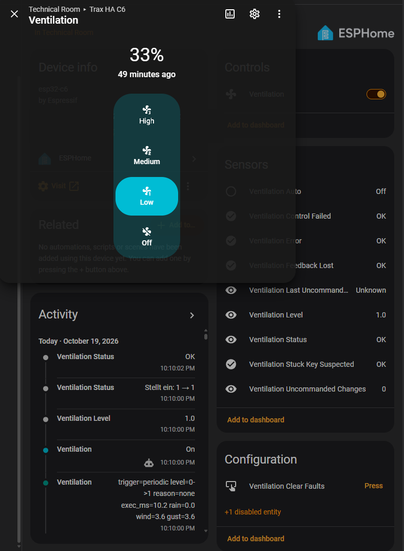
Device page with the fan dialog. The activity log shows a real command from an automation: fan on at 22:10:00, LED feedback for stage 1 in the same second, status “OK” at 22:10:02.
The fan dialog offers Off / Low / Medium / High: stages 0–3, 0 / 33 / 66 / 100 %.
The status sensor uses German texts:
Status
Meaning
OK
Idle, stage confirmed by the unit's LEDs
Stellt ein: 1 → 2
Adjusting from stage 1 to 2
Aus (oder 24 V fehlt)
Unit is off – or there is no 24 V / no LED signal at all
Gestört/unbekannt – keine Rückmeldung
A key press caused no LED change (check 24 V, wiring, EIN)
Steuerung fehlgeschlagen
Target not reached after all retries
Verdacht Dauerdruck – Hardware prüfen (T2)
Stage moved against the pressed direction – possible stuck key
Start
Booting; key presses are blocked until the first sync
Tested with ESPHome 2026.9.1 on a XIAO ESP32-C6.
Control logic: A requested speed becomes single key presses (300 ms pulse, 700 ms pause). After each press the firmware waits up to 2 s for the stage LEDs to change. If they don't, it retries with back-off (1/2/4/4 s, max. 10 presses). On boot the entity syncs to the real stage without pressing anything.
yaml
# Example automation actionaction: fan.set_percentage
target:
entity_id: fan.trax_ha_c6_ventilation
data:
percentage: 66# 33 = stage 1, 66 = stage 2, 100 = stage 3; use fan.turn_off for off
LED feedback is immediate. The fans themselves need about 30–70 s to reach their speed.
3. Enclosure
Size: 80.7 × 69.8 × 24.1 mm, 95.8 mm long including the two wall-mounting tabs (slots for Ø 4 screws).
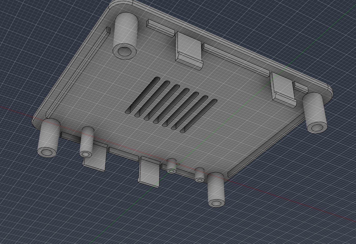
No hardware needed: pins on the bosses locate the PCB, four hold-downs in the lid clamp it, and the lid snaps into four windows. To open it, push each hook inwards through its window with a small screwdriver.
Openings: nine labelled wire holes (Ø 3.9 mm, aligned with the terminal entries), a USB-C opening, pin holes for RESET/BOOT (paper clip) and a light pipe for “24V OK”.
Printing (tested on a Bambu Lab P2S, PLA): 0.2 mm layers, 4 walls, 4 bottom layers, 15 % infill, no supports, lid printed top-down. About 1 h 25 min and 49 g. Use PETG for warm locations.
Files:
CentralVentilationCase_BambuStudio_P2S_PLA.3mf: ready-to-print Bambu Studio project
Bench replica of the unit's terminal board: DIP switches pull AUS0–4 to 0 V, LEDs show EIN0/EIN1. Not manufactured or tested yet. LED polarities in the assembly preview are unverified.
Supply voltage: designed to EEE-INST-002 derating for 21.6–30 V. Above 27.5 V the output optocouplers U6/U7 exceed the derating limit (absolute max 35 V), and above ≈ 29 V so do R1–R5. Spikes on the 24 V line have not been measured.
EIN input current of the unit has not been measured. It decides whether R20/R21 = 1 kΩ is optimal (up to 4 mA the unit still sees ≥ 19 V).
Short circuit on EIN is tolerable for the pulse length only: a permanent short would put 0.5 W into R20/R21, which are rated 0.125 W.
A stuck key is not single-fault safe: a shorted Q1/Q2 or U6/U7 would hold a button down. The firmware only detects it indirectly (stuck_key_suspected).
Tools
tools/qa and tools/verifikation contain the scripts that generated and verified schematic and layout:
KiCad 10 Python
ngspice via the KiCad DLL
gerbonara / shapely
Local paths are replaced by <PROJEKT> / <HOME>; adjust them before running.
License
MIT: free to use, build, modify and share, also commercially, as long as the license notice is kept. Symbols and footprints embedded in the KiCad files come from the KiCad libraries (CC-BY-SA 4.0 with the KiCad design exception) and do not restrict your own boards.
Disclaimer
Dimplex and ZL 400 VF are trademarks of Glen Dimplex Deutschland GmbH; XIAO is a trademark of Seeed Studio. This project is not affiliated with or endorsed by either company.
ESPHome controller for Dimplex ZL 300/400 VF ventilation units – isolated 24 V I/O, XIAO ESP32-C6, KiCad PCB, 3D-printed case. | ESPHome-Steuerung für Dimplex-Lüftungsgeräte ZL 300/400 VF mit Home Assistant.
A circuit board for old telephones to come back to life. Plug one or two phones in, and you can call the other phone, use bluetooth, connect to others via voip, and do a variety of other things with a plain old rotary…
137 parts46
Questions
How big is the ESP24V HA XIAO PCB?
It measures 75 × 64 mm and has 2 copper layers, 1.6 mm thick.
What parts does the ESP24V HA XIAO use?
47 parts, built around the EL817-S1, 1N4148W and MMBT3906. The full list of its parts is on this page, with links to each part's symbol and footprint where PCBKit's library has them.
Where can I download the ESP24V HA XIAO KiCad files?
From the Traxes/dimplex-zl400-esphome repository on GitHub, at the commit this page was made from: the board is hardware/controller-v3/kicad/ESP24V_HA_XIAO.kicad_pcb and its schematic hardware/controller-v3/kicad/ESP24V_HA_XIAO.kicad_sch. PCBKit opens the board in the browser, with nothing to install.
Can I use the ESP24V HA XIAO design in my own project?
Its repository publishes it under the MIT licence: you may reuse it on that licence's terms (keep the author's notice, and for a copyleft licence share your changes alike).