2 layers17.4 × 51.4 mm
Retro uart
rkujawa/retro-uart
Retro-fitting 16C750E into DIP socket! For all your retro hardware project needs.
17 partsGPL-3.0

 TjarkG/RPM41113
Reverse Engineering of the Vaisala RPM411 Pressur Sensor for the RS41 Radiosonde
RPM411 is an open-source printed circuit board by TjarkG, from the TjarkG/RPM411 repository on GitHub. It is a 2-layer board with 88 parts on 78 nets.
It is built around the TS5A9411DCK, 74LVC1G32Z and 74LVC3G04DC, with the TLV70030DDC among its other parts. Its parts include 34 capacitors, 34 resistors, 7 ICs, 4 inductors and 2 connectors. It belongs with the STM32 boards of this library.


Reverse Engineering of the Vaisala RPM411 Pressur Sensor for the RS41 Radiosonde
For information about the RS41 see Bajzos website, for schematics of it the Radiosonde Hardware Repo.
The Schematic is in Kicad format, the Parts overlay in svg and can be edited with Inkscape. Some scans in jpeg are provided too.
Pull requests with improvements, translations and bug fixes are welcome!
The sonde is to be divided into three functional blocks, which are seperated by dotted lines in the Schematic.
Microcontroller (hidden by a shield with sticker) and Connector are on the Sonde facing side of the PCB, while the Front end usses almost the entire other side, with its power supply weged in the bottom left corner.
Reverse engineering is simpliefied by the fact that the blocks are essentialy smaller Versions of there RS41 counterparts, sharing many parts. A significant Part of this describtion is therfore the same as for the RS41 with different Part numbers.
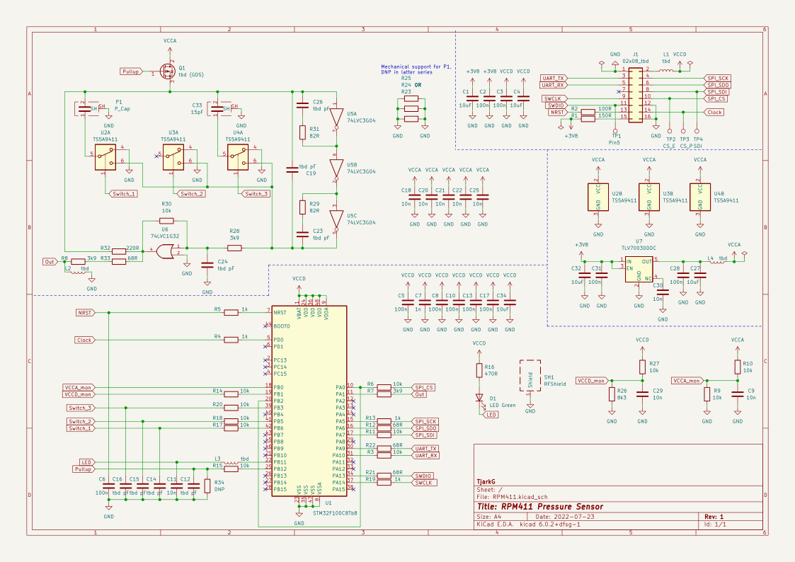
The powersupply (middle right) consists of a Low Dropout Regulator
TVS70030 from TI (U7), generating 3.3V for the frontend (the MCU is supplyed directly by the Sonde). Pin 4 of the LDO, which is NC according to the datasheet, is decoupled against ground, probably so that pin compatible versions like the MAX8887 can be used.
The microcontroller is a STM32F100C8 U1 from ST in LQFP48 package, the same model as in the Sonde itself, running from an internall clock. Like in the RS41, RC low pass filters are present at many outputs and resistors at many inputs
Electrically, the Frontend is very similar to the RS41's Humindity Messurment, but simplified because there is no temperature Messurment or Heating and all Components are on the PCB. In addition to the Pressure Sensor P1, a 15pF reference Capacitor C33 is available.
The frontend consists of a ring oscillator, whose frequency is varied by variable impedances (e.g. the sensors) inserted into the feedback path with the help of analog switches.
Each ring oscillator is formed by a 74LVC3G04 Triple Inverter U5. The three inverters are connected in series. The first and third inverter are feedbacked directly via an RC series element C26/R31, R29/C23, the entire ring oscillator via a capacitor C19. The ring oscillators can be pulled to +3V by a P-channel MOSFET Q1 at the first inverter with separate control, which corresponds to ground at the output, to deactivate them.
The feedback path consists of a 74LVC1G32 Or-Gate U6 used as an Buffer and two resistors R28 and R30, which probably are used for the fine tuning of the resonance frequency. This is followed by three single pole single throw (SPST) switches TS5A9411 U2-4, the NO of which is connected to the output of the buffer and which switch the measuring and reference capacitor either into the feedback network or to ground. U3 has no connection between COM and the input of the first buffer, where there should normally be a reference capacitor, so this switch does not serve any obvious purpose. However, since it is driven in software like the other two, it can be assumed that the switches have an example-independent non-linear effect on the feedback frequency measured at this switch to compensate for it. Parallel to the switches, fixed feedback is applied via the resistor R32.
The measurement output is sent to the MCU via R8 and R33.
J1 connects the Board to the RS41's SPI bus, a clock and a Chip Select, one of which is shared with the EEPROM, as well as 3V MCU voltage shared with the STM32 on the Sonde and the EEPROM and 3.8V from the boost converter used to supply the Frontend via U7. From the six Pins that aren't connected on the RS41, five are used for an SWD interface, the MCU Reset pin and an UART and one remains unused.
| Qty | Value | Footprint | References |
|---|---|---|---|
| 12 | 10k | Resistor_SMD:R_0402_1005Metric | R3, R6, R9, R10, R11, R14, R15, R17, R18, R20, R27, R30 |
| 10 | 100n | Capacitor_SMD:C_0402_1005Metric | C2, C3, C5, C6, C8, C10, C13, C17, C28, C31 |
| 9 | 10n | Capacitor_SMD:C_0402_1005Metric | C9, C11, C18, C20, C21, C22, C25, C29, C30 |
| 8 | tbd pF | Capacitor_SMD:C_0402_1005Metric | C12, C14, C15, C16, C19, C23, C24, C26 |
| 5 | 10uF | Capacitor_SMD:C_0805_2012Metric | C1, C4, C27, C32, C34 |
| 4 | 1k | Resistor_SMD:R_0402_1005Metric | R4, R5, R13, R19 |
| 4 | 68R | Resistor_SMD:R_0402_1005Metric | R12, R21, R22, R33 |
| 4 | tbd | Inductor_SMD:L_0402_1005Metric | L1, L2, L3, L4 |
| 3 | 0R | Resistor_SMD:R_0402_1005Metric | R23, R24, R25 |
| 3 | 3k9 | Resistor_SMD:R_0402_1005Metric | R7, R8, R28 |
| 3 | TS5A9411 | Package_TO_SOT_SMD:SOT-363_SC-70-6 | U2, U3, U4 |
| 2 | 82R | Resistor_SMD:R_0402_1005Metric | R29, R31 |
| 1 | 02x08_tbd | Connector_PinHeader_1.00mm:PinHeader_2x08_P1.00mm_Vertical | J1 |
| 1 | 100R | Resistor_SMD:R_0402_1005Metric | R2 |
| 1 | 150R | Resistor_SMD:R_0402_1005Metric | R1 |
| 1 | 15pF | RPM411:Cap_Shield | C33 |
| 1 | 1n | Capacitor_SMD:C_0402_1005Metric | C7 |
| 1 | 220R | Resistor_SMD:R_0402_1005Metric | R32 |
| 1 | 470R | Resistor_SMD:R_0402_1005Metric | R16 |
| 1 | 74LVC1G32 | Package_TO_SOT_SMD:SOT-353_SC-70-5 | U6 |
| 1 | 74LVC3G04 | Package_SO:SSOP-8_3.95x5.21x3.27mm_P1.27mm | U5 |
| 1 | 8k3 | Resistor_SMD:R_0402_1005Metric | R26 |
| 1 | CS_E | TestPoint:TestPoint_Pad_D1.0mm | TP2 |
| 1 | CS_P | TestPoint:TestPoint_Pad_D1.0mm | TP3 |
| 1 | DNP | Resistor_SMD:R_0402_1005Metric | R34 |
| 1 | LED Green | LED_SMD:LED_0805_2012Metric | D1 |
| 1 | P_Cap | RPM411:Pressure_Cap | P1 |
| 1 | Pin5 | TestPoint:TestPoint_Pad_D1.0mm | TP1 |
| 1 | RFShield | RPM411:RMP411_Shield | SH1 |
| 1 | SDI | TestPoint:TestPoint_Pad_D1.0mm | TP4 |
| 1 | STM32F100C8Tb8 | Package_QFP:LQFP-48_7x7mm_P0.5mm | U1 |
| 1 | TLV70030DDC | Package_TO_SOT_SMD:SOT-23-5 | U7 |
| 1 | tbd (GDS) | Package_TO_SOT_SMD:SOT-523 | Q1 |
rkujawa/retro-uart
Retro-fitting 16C750E into DIP socket! For all your retro hardware project needs.


Ledger-Donjon/silicon-toaster
SiliconToaster is an open-source hardware electromagnetic fault injection device, designed for hardware security research. It has the following features:

acha666/RP2040_ToolheadPCB_SB
A Toolhead PCB for VORON StealthBurner based on RP2040


Mhouranix1125/DMG-KGDU-10-Plus-FRAM-Upgraded-PCB
First: Shoutout to HDR. His work was extremely vital in completing this project. Take a look at his github and check out some of the cool projects he has worked on!

88 parts, built around the TS5A9411DCK, 74LVC1G32Z, 74LVC3G04DC and TLV70030DDC. The full list of its parts is on this page, with links to each part's symbol and footprint where PCBKit's library has them.
From the TjarkG/RPM411 repository on GitHub, at the commit this page was made from: the board is schematic/RPM411.kicad_pcb and its schematic schematic/RPM411.kicad_sch. PCBKit opens the board in the browser, with nothing to install.
Its repository states no licence, so its author keeps all rights: ask TjarkG before reusing the design.