
2 layers30 × 43 mm
Hayashi light control
Ledger-Donjon/hayashi-light-remote
USB remote control dongle for Hayashi LA-150CE halogen lamp
34 parts2

SiliconToaster is an open-source hardware electromagnetic fault injection device, designed for hardware security research. It has the following features:
Emfi is an open-source printed circuit board by Ledger-Donjon, from the Ledger-Donjon/silicon-toaster repository on GitHub, published under the LGPL-3.0 licence. It is a 2-layer board of 132.5 × 38 mm with 81 parts on 95 nets, routed with 377 tracks and 331 vias.
It is built around the IKW40N120H3FKSA1, FT232RL and MCP1407-E/SN, with the 74LVC1G32Z, SCS-200LD and MBRM140T3 among its other parts. Its parts include 42 capacitors, 11 resistors, 9 diodes, 8 ICs and 6 connectors. It belongs with the STM32 boards of this library.


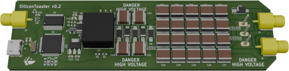
SiliconToaster is an open-source hardware electromagnetic fault injection device, designed for hardware security research. It has the following features:
Warning: this device is experimental and for research purpose only. High-voltage is exposed on the PCB, which can present electrical hazard. Use with caution and at your own risk. Beware that the coil body is connected to the high potential, NOT at the ground. Also, the exposed capacitor bank stores an important amount of energy.
To build the firmware, rust shall be installed on your system (see instructions for installation).
The rust toolchain for Armv6-M Thumb must be installed:
rustup target add thumbv6m-none-eabiThe firmware can then be compiled using cargo:
cd firmware
cargo objcopy --release --bin silicontoaster -- -O binary silicontoaster.bin
To flash the device, stm32flash utility is required. The MCU bootloader can be enabled by shorting the header close to the USB connector using a jumper, before connecting the PCB on USB. Then the following command will flash the MCU (replace /dev/ttyUSB0 with the serial device in your situation):
stm32flash -w silicontoaster.bin -v -g 0 /dev/ttyUSB0Alternatively, a makefile can run those steps:
cd firmware
make all
make flash
To enable device recognition, the FTDI USB-serial converter must be flashed using ftdi_eeprom tool. Warning: be sure no other FTDI device is connected before running this command!
cd ftdi
bash flash.shTo use the device, run python3 silicontoaster/tool.py. This will run a graphical interface that allows setting the operating voltage and display in real-time the voltage in the capacitors bank.
When running for the first time, configure the charge pump PID settings to Kp, Ki and Kd to 1. Be sure to have the jumper J5 installed (position closest to the USB).
The provided calibration values should work fine by default, it is not necessary to calibrate the device by yourself unless you want more accurate measurements.
This work was published in our Paper and presented during Hardwear.io 2020 conference.
SiliconToaster is released under GNU Lesser General Public License version 3 (LGPLv3). See LICENSE and LICENSE.LESSER for license detail.
| Qty | Value | Footprint | References |
|---|---|---|---|
| 20 | 100n | Capacitor_SMD:C_2225_5664Metric_Pad1.80x6.60mm_HandSolder | C22, C23, C24, C25, C26, C27, C28, C29, C30, C31, C32, C33, C34, C35, C36, C37 +4 |
| 10 | 100n | Capacitor_SMD:C_0603_1608Metric | C1, C2, C3, C4, C5, C8, C9, C16, C17, C42 |
| 7 | 2.2µ | Capacitor_SMD:C_0603_1608Metric | C6, C7, C10, C11, C12, C13, C14 |
| 6 | US1K-E3/61T | Diode_SMD:D_SMA_Handsoldering | D1, D2, D3, D4, D6, D9 |
| 4 | 10k | Resistor_SMD:R_0603_1608Metric | R1, R3, R4, R7 |
| 4 | 150n | Capacitor_SMD:C_2225_5664Metric_Pad1.80x6.60mm_HandSolder | C18, C19, C20, C21 |
| 3 | Conn_Coaxial | mykicadlibs:SAMTEC_SMA_J_P_H_ST_EM3 | J2, J3, J6 |
| 2 | 10M | Resistor_SMD:R_0603_1608Metric | R2, R11 |
| 2 | 64.9 | Resistor_SMD:R_0603_1608Metric | R8, R10 |
| 2 | LD1117S33TR_SOT223 | Package_TO_SOT_SMD:SOT-223-3_TabPin2 | U4, U5 |
| 1 | 10µ | Inductor_SMD:L_1812_4532Metric | L2 |
| 1 | 22.1k | Resistor_SMD:R_0603_1608Metric | R5 |
| 1 | 22u | Capacitor_SMD:C_0805_2012Metric | C15 |
| 1 | 2k | Resistor_SMD:R_0603_1608Metric | R6 |
| 1 | 4.99 | Resistor_SMD:R_0603_1608Metric | R9 |
| 1 | 74LVC1G32 | Package_TO_SOT_SMD:SOT-353_SC-70-5 | U8 |
| 1 | Conn_01x02 | Connector_PinHeader_2.54mm:PinHeader_1x02_P2.54mm_Vertical | J4 |
| 1 | Conn_01x03 | Connector_PinHeader_2.54mm:PinHeader_1x03_P2.54mm_Vertical | J5 |
| 1 | DUNGEON_LOGO | mykicadlibs:donjon-2000 | LOGO1 |
| 1 | FT232RL | Package_SO:SSOP-28_5.3x10.2mm_P0.65mm | U2 |
| 1 | Ferrite_Bead_Small | Inductor_SMD:L_0603_1608Metric | L1 |
| 1 | IKW40N120H3FKSA1 | mykicadlibs:TO-247-3_Horizontal_TabDown_NoTabDrill | Q2 |
| 1 | MBRM140T3 | Diode_SMD:D_Powermite_AK | D5 |
| 1 | MCP1407-E/SN | Package_SO:SOIC-8_3.9x4.9mm_P1.27mm | U6 |
| 1 | MIC2288 | Package_TO_SOT_SMD:SOT-23-5 | U3 |
| 1 | SCS-200LD | mykicadlibs:SCS-200L | U7 |
| 1 | STM32F205RETx | Package_QFP:LQFP-64_10x10mm_P0.5mm | U1 |
| 1 | STT6N3LLH6 | Package_TO_SOT_SMD:SOT-23-6 | Q1 |
| 1 | USB_B_Micro | Connector_USB:USB_Micro-B_Wuerth_629105150521 | J1 |
| 1 | green | Diode_SMD:D_0603_1608Metric | D8 |
| 1 | red | Diode_SMD:D_0603_1608Metric | D7 |
Ledger-Donjon/hayashi-light-remote
USB remote control dongle for Hayashi LA-150CE halogen lamp

mariusenglund/three-phase-inverter
Materials for enhancing the DC-to-AC converter that was designed as part of our bachelor's thesis in the spring of 2023.


ratmuds/spark
The PCB files for this project. The gerber and other PCBA files are in the production folder.

TEALab-UF/bldc_esc_pcb
This repo contains the KiCAD files of the schematic and PCB layout for the TEACar BLDC motor controller

ANSHUMANDOCX/Spot-Welder-with-MCU
this is a spot welder for 18650 batteries made using mosfets along with a atemga328p and rotary encoder along with a display and a 12v lead acid battery

It measures 132.5 × 38 mm and has 2 copper layers, 1.6 mm thick.
81 parts, built around the IKW40N120H3FKSA1, FT232RL, MCP1407-E/SN and 74LVC1G32Z. The full list of its parts is on this page, with links to each part's symbol and footprint where PCBKit's library has them.
From the Ledger-Donjon/silicon-toaster repository on GitHub, at the commit this page was made from: the board is hardware/emfi.kicad_pcb and its schematic hardware/analog.kicad_sch. PCBKit opens the board in the browser, with nothing to install.
Its repository publishes it under the LGPL-3.0 licence: you may reuse it on that licence's terms (keep the author's notice, and for a copyleft licence share your changes alike).