2 layers30 × 15 mm
TFASPDIMU02
ThunderFly-aerospace/TFASPDIMU02
I²C bus differential pressure sensor with IMU and Magnetometer.
43 parts3GPL-3.0

 ThunderFly-aerospace/TFASPDIMU011
SPI or I²C differential pressure sensor and IMU unit.
TFASPDIMU01 is an open-source printed circuit board by ThunderFly-aerospace, from the ThunderFly-aerospace/TFASPDIMU01 repository on GitHub, published under the GPL-3.0 licence. It is a 2-layer board of 36 × 14 mm with 26 parts on 35 nets, routed with 344 tracks and 59 vias.
It is built around the ICM-20948, MIC5504-1.8YM5-TR and MIC5504-3.3YM5-TR, with the TXS0108EPW and SM07B-GHS-TB among its other parts. Its parts include 11 capacitors, 8 resistors, 5 ICs, 1 diode and 1 connector. It belongs with the sensors and measurement boards of this library.


ThunderFly TFASPDIMU01 is SPI/I2C sensor board equipped with a differential pressure sensor (Senserion SDP3x) and 9-axis motion tracking sensor (ICM-20948). Board is equipped with 7pin JST-GH connector. The sensor board is designed for multiple uses. It can be used as a self-adjusting anemometer WINDGAUGE03 or as an airspeed sensor for UAVs with optional function as the external magnetometer.
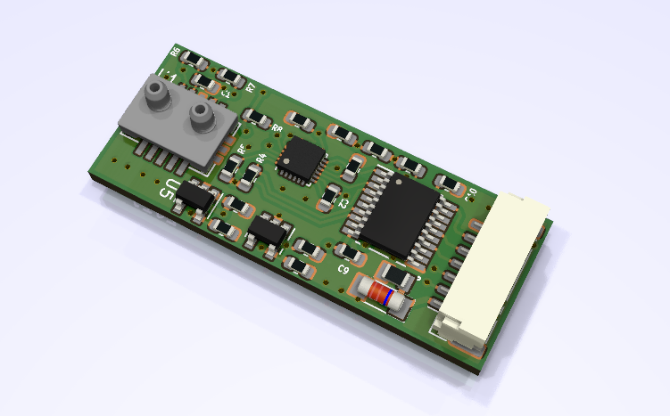
TFASPDIMU is commercially available from ThunderFly s.r.o., write an email to info@thunderfly.cz or shop at Tindie store.
SDP3x
ICM-20948
Ground control station anemometer WINDGAUGE03
Our TFSLOT senzor is an airspeed sensor for use mainly on UAV. Due to 3D printed case it is possible to optimalize part according to the location of sensor on UAV and tune their characteristics. First use of this sensor was on our autogyro TF-G2.

More details about this solution is available in the repository TFSLOT01.
Symmetric variant of TFSLOT sensor for different mounting options TFPIPE01.
This anemometer should also based on venturi effect. Thanks to an clever design, it will measure the wind speed from all directions (without knowing the direction).
In case of mounting on rotation slip-ring bearing the sensor could sense air AoA of the vehicle. Due to ability to turn in direction of airflow. The turnig direction could be sensed differentialy to position of aircraft by IMU embedded in the TFASPDIMU01 sensor.
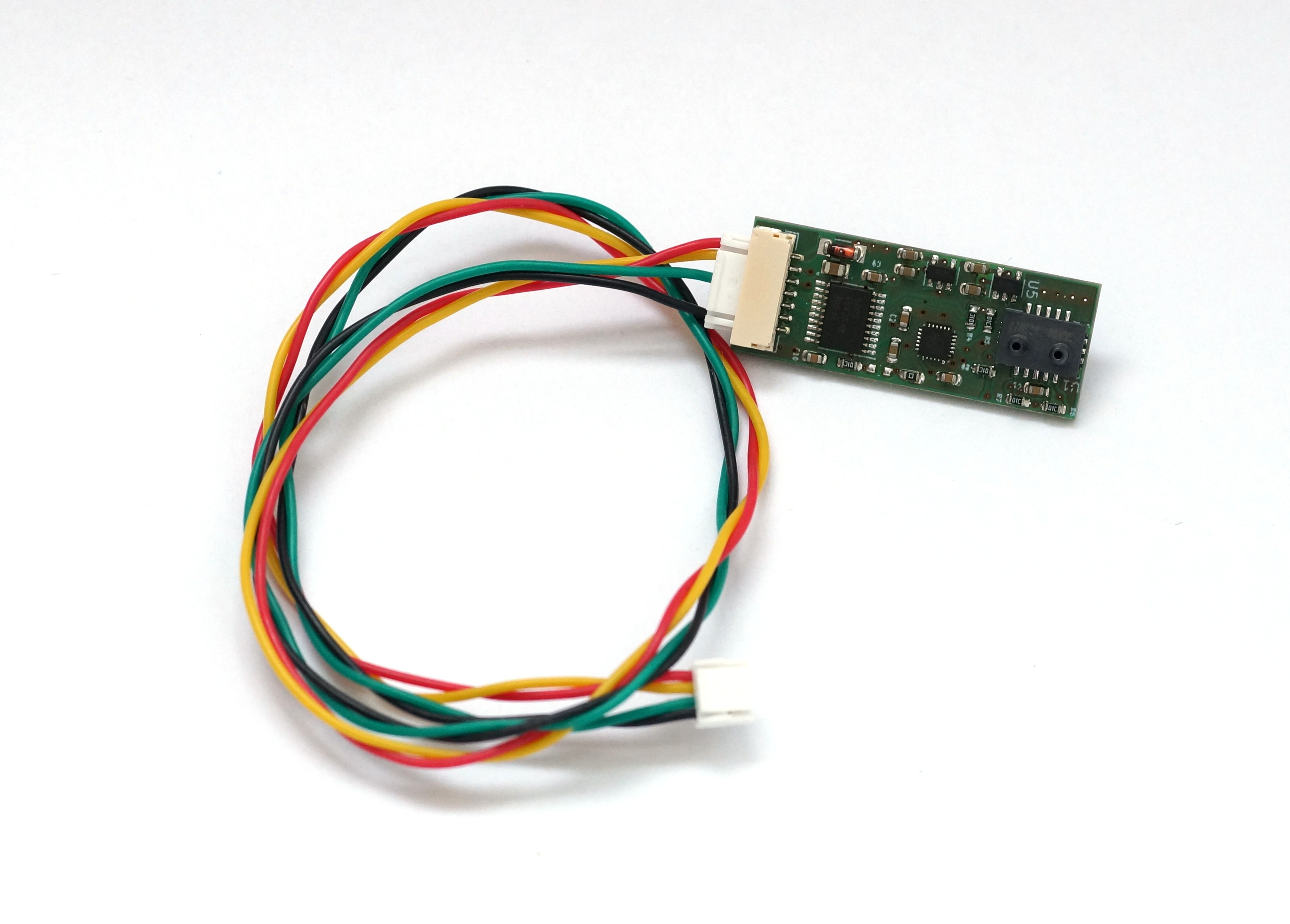
Full schema is avialible in PDF
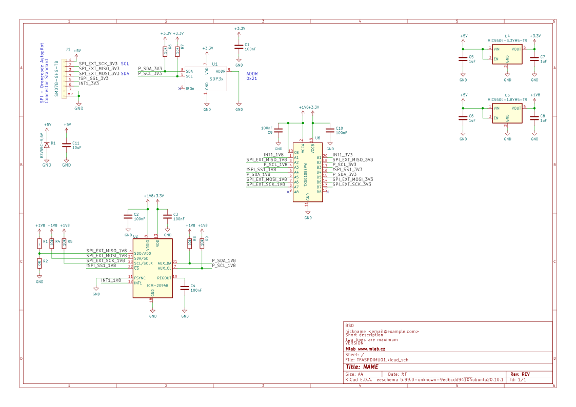
** IMG - technical draft **
| Pin # | I2C | SPI |
|---|---|---|
| 1 | +5V | +5V |
| 2 | SCL | SCK |
| 3 | -- | MISO |
| 4 | SDA | MOSI |
| 5 | -- | CS |
| 6 | INT | INT |
| 7 | GND | GND |
Due to the possible wider use of the sensor, a standard pixhawk pinout is not used.
To increase the transmission quality, it is recommended to create pairs SDA,GND and SCL,+5V on the cable (as shown in image)
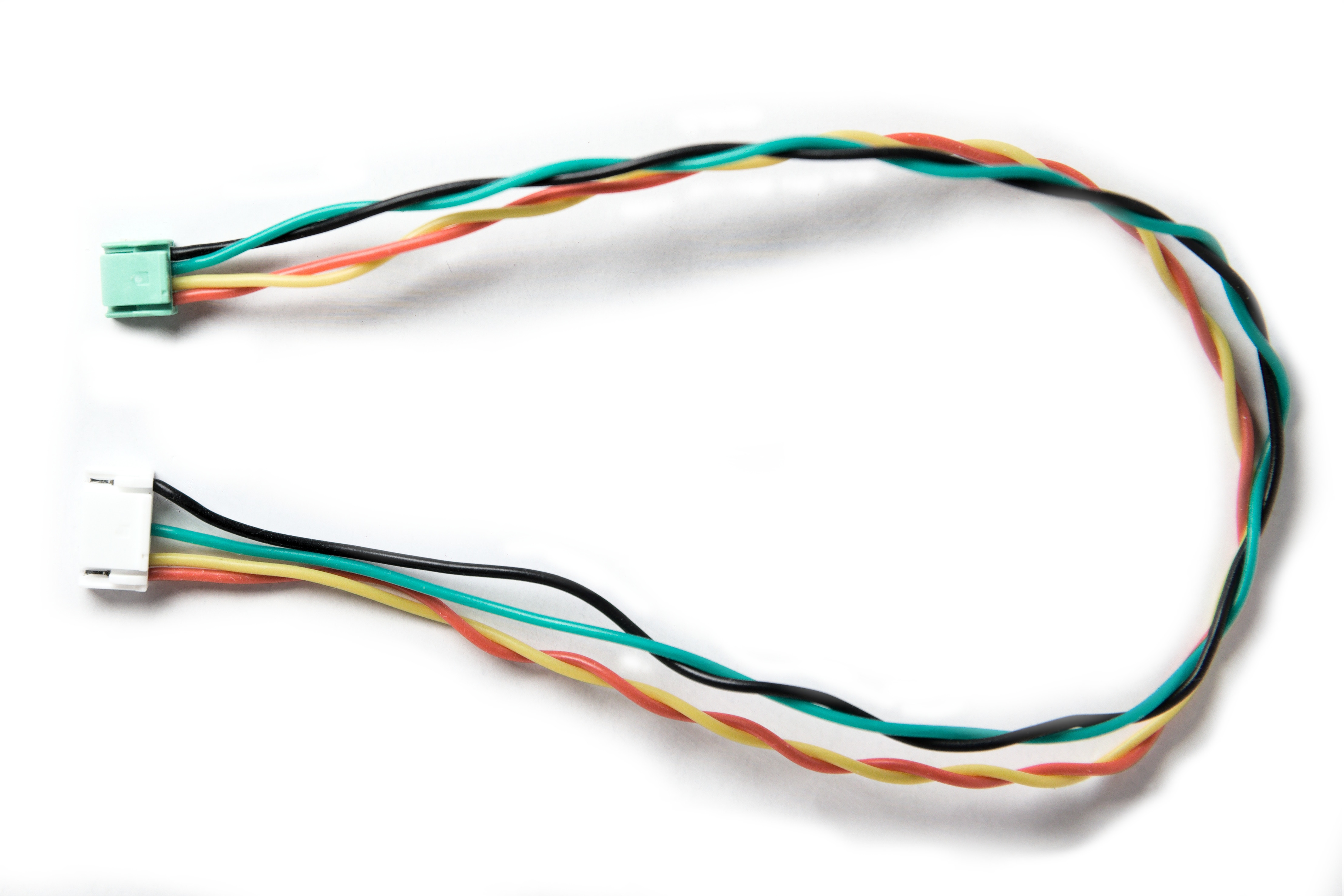
| TFASPDIMU01 Pin | Sigal | Pixhawk | Color |
|---|---|---|---|
| 1 | +5V | 1 | Red |
| 2 | SCL | 2 | Yellow |
| 4 | SDA | 3 | Green |
| 7 | GND | 4 | Black |
Pixhawk pinout is listed according to the Pixhawk connector standard.
For reading data from the sensor, we have prepared a python script in PyMLAB library that uses the pySMBus to readout data. It can be used directly from a computer with a corresponding converter (for example MLAB USBI2C01A) or with one-board computers (Odroid, raspberry and similar) that have own smbus output.
Calibration can be verified by mounting of an anemometer to car roof and comparing it to speed obtained from GPS (gpsd). This needs to be done in windless weather.
We are now working on implementation of driver into PX4 stack.
Main usage of this sensor is as airspeed sensor. It can be also used as an external magnetometer and thermometer.
We are currently unable to implement the sensor in the Ardupilot flight stack. However, we will be happy to provide assistance with implementation. You can contact us
TODO
| Qty | Value | Footprint | References |
|---|---|---|---|
| 6 | 100nF | Mlab_R:SMD-0603 | C1, C2, C3, C4, C9, C10 |
| 6 | 10k | Mlab_R:SMD-0603 | R4, R5, R6, R7, R8, R9 |
| 4 | 1uF | Mlab_R:SMD-0603 | C5, C6, C7, C8 |
| 1 | - | Mlab_R:SMD-0603 | R1 |
| 1 | 0R | Mlab_R:SMD-0603 | R2 |
| 1 | 10uF | Mlab_R:SMD-0805 | C11 |
| 1 | BZV55C-5,6V | Diode_SMD:D_MiniMELF | D1 |
| 1 | ICM-20948 | Sensor_Motion:InvenSense_QFN-24_3x3mm_P0.4mm | U2 |
| 1 | MIC5504-1.8YM5-TR | Package_TO_SOT_SMD:SOT-23-5 | U5 |
| 1 | MIC5504-3.3YM5-TR | Package_TO_SOT_SMD:SOT-23-5 | U4 |
| 1 | SDP3x | Mlab_IO:SDP3x | U1 |
| 1 | SM07B-GHS-TB | Connector_JST:JST_GH_SM07B-GHS-TB_1x07-1MP_P1.25mm_Horizontal | J1 |
| 1 | TXS0108EPW | Package_SO:TSSOP-20_4.4x6.5mm_P0.65mm | U6 |
ThunderFly-aerospace/TFASPDIMU02
I²C bus differential pressure sensor with IMU and Magnetometer.


Case-Rocket-Team/PayloadPrototypeBoard2021
Prototype Payload Board for the 2021 ESRA Payload using Parafoil Guidance. KiCad Project

mlab-modules/DATALOGGER02
Arduino based data logger with LoRa IoT interface.


williamjroche/Drone_Flight_Controller
This is a GPS-Denied Autonomous Drone that uses computer vision to fly with radio transmission override. Autonomy is a work in progress.

ThunderFly-aerospace/TFUNIPAYLOAD01
Universal interface for TF-ATMON sensor payload.
It measures 36 × 14 mm and has 2 copper layers, 1.6 mm thick.
26 parts, built around the ICM-20948, MIC5504-1.8YM5-TR, MIC5504-3.3YM5-TR and TXS0108EPW. The full list of its parts is on this page, with links to each part's symbol and footprint where PCBKit's library has them.
From the ThunderFly-aerospace/TFASPDIMU01 repository on GitHub, at the commit this page was made from: the board is hw/sch_pcb/TFASPDIMU01.kicad_pcb and its schematic hw/sch_pcb/TFASPDIMU01.kicad_sch. PCBKit opens the board in the browser, with nothing to install.
Its repository publishes it under the GPL-3.0 licence: you may reuse it on that licence's terms (keep the author's notice, and for a copyleft licence share your changes alike).